|
 3-Way High Efficiency Speaker
(Lavoce, Dynaudio, Foster 3-way. October-2023)
LCR MTM 3-Channel Speaker
(Three MTM Speakers in One. July-2023)
Mini7bt - A Minimus 7 Portable Bluetooth Speaker
(Minimus 7 and Dayton Audio. Spring-2022)
2-Way Ribbon Tweeter Speakers
(Vifa and Pioneer. May-2020)
Transmission Line Speakers
(Aborted attempt at a TL. September-2012)
Acoustic Research AR-4x Rehab
(Rehab of a garage sale find. January-2016)
Infinity RS-4000 Rehab
(Rehab of a garage sale find. June-2015)
Polaris
(A tall, thin, upwards firing omnidirectional speaker. May-2010)
Shiva_PR15
(A powered subwoofer using a 12" driver and 15" passive radiator. Jan-2010)
Can-Less
(A computer speaker; redux. December-2005)
Can-Can
(A computer speaker in a light canister. Jan-2005)
Sonosub
(10" vented subwoofer in a cardboard tube, powered by a Parapix amp. May-1999)
MTM Center Channel Speaker
(A Madisound design. Nov-1997)
2-way Surround Speakers
(5" woofer and 1" tweeter. July 1997)
3-piece mini system
(6" DVC bass module mated to 4" car speaker. June 1997)
3-way Vented Floorstanding Speaker
(vented 10" woofer, 5" mid and 1" tweeter in a 4
ft tower. Summer 1995)
NHT1259 Subwoofer
(A 12" woofer in a sealed architectural pedestal. Winter 1994-95)
Inexpensive Speaker Stands
(Particle board, sand and spray paint. Fall 1994)
2-way satellite
(6.5" woofer and 1" tweeter. Summer/Fall 1994)
| Audio Electronics Related Projects |
900 MHz Audio Receiver
(Better use for bad headphones. Jan-2008)
Buster - A Simple Guitar Amp
(Perfect for the beginner. Jan-2010)
A PC-based Audio Console
(Use a PC to play tunes. Jan-2010)
LM-12 Amp
(Bridged LM-12 opamps. Aug-2003)
CeeDeePee
(A CD player and FM tuner from spare computer parts. Oct-2002)
Quad 2000 4-Channel Amp
(Premade modules by Marantz. May-1998)
Zen Amp and Bride of Zen Preamp
(by Nelson Pass. Apr-1997)
Using Wood in Speakers FAQ
(Work in progress)
MDF FAQ for speaker builders
Woodworking Tools for the DYIer
(HomeTheaterHiFi.com Oct-1998)
Some Thoughts on Cabinet Finished for DIY Speakers
Large Grills Made Easy
Some Parts Suppliers
(Outdated)
DIY Audio Related URLs
Veneering Primer
(by Keith Lahteine)
How to get a Black Piano Finish
(by DYI Loudspeaker List members)
Sonotube FAQ
(by Gordon McGill)
Excerpts from the Bass List
(Oldies but Goodies)
DIY Loudspeaker List Archives
|
|
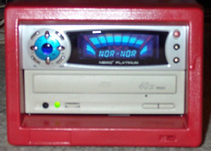
CeeDeePee
A
recycled CD-ROM drive, FM tuner and Sound Processor
Introduction
What do
you do with spare CD-ROM drives ? Over the past few years,
I've collected a large number of spare computer parts - including
cards, cables, and drives; all of them in perfectly working
order. Some items become obsolete (such as ISA cards) and
eventually find their way to the trash. CD-ROM drives are
generally useful - it's usually possible to mount them in
a PC if you have spare 5-1/4 inch bays and available IDE channels.
The older slower drives are not too useful for data access
but can still serve as dedicated audio playback devices.
While rumaging
through my spare parts one day, I noticed that one spare CD-ROM
drive had two buttons on its faceplate. Most CD-ROM drives
have only a single "Eject" button. This drive had
one button with icons for "Eject/Stop" and the other
for "Play/Forward". Looking around, I saw that one
of my DVD drives also had this extra button. What this means
is that this drive can play audio CDs without the aid of a
host CPU. In other words, this drive is also a stand-alone
CD player. Spare CD-ROM drives that collect dust have little
use; but spare CD players are always useful to someone who
has a speaker building hobby ! :)
Another
spare part I have is an old metal case that used to house
an 8mm DAT backup tape drive. This case looked like it would
hold the CD-ROM drive nicely. The unit measures 15-1/2 inches
deep, 7 inches wide and 5-1/2 inches tall. The front has openings
for two 5-1/4 inch devices. Inside are pre-drilled supports
to hold the 2 devices in the bay (these used to hold the SCSI
DAT drives). After accounting for the depth of the CD-ROM
drive (about 8 inches), there is sufficient room in the rear
for a power supply. If I mount the CD-ROM drive in the lower
of the 2 bays, there is plenty of room above it to house some
sort of control and power amplifier. I can then cover the
upper device bay on the spare 5-1/4 inch faceplate.
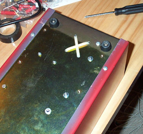
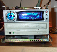
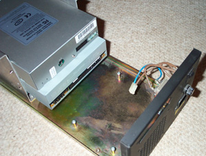 [This picture shows the 2 devices mounted to the existing
supports in the case. The empty are is where the amplifer
and power supply must sit. There's some existing power wiring
from the EMI filter and fuse.]
[This picture shows the 2 devices mounted to the existing
supports in the case. The empty are is where the amplifer
and power supply must sit. There's some existing power wiring
from the EMI filter and fuse.]
Then came
another twist. When I told my brother what I was up to, he
gave me a NewQ
3379 Platinum tuner/preamp unit from his spare parts bin.
Like the CD-ROM drive, the NewQ 3379 is housed in a 5-1/4
inch chassis and is designed to be mounted in a device bay.
By wiring a PC's sound card's output through the NewQ 3379's
preamp stage, the the NewQ 3379 can further process all PC
audio outputs with various surround, hall and reverb effects.
The NewQ 3379 also comes with a remote control.
Parameters
At this
point, I should mention my project parameters. As a DIY hobbiest,
I firmly believe in defining a set of parameters before beginning
any project. If I had infinite resources (time, money, patience,
etc.) I would probably never finish any projects. Feature
creep would guarantee endless cycles of changes. Setting goals
helps control the building process and defines an end state.
The main
characteristics of this project are:
- This
is mainly a recycling effort. I don't need another
CD player and if I did need one, I could just buy one off
the shelf that would give me lots of useful features. But
I do have lots of idle "stuff" so let's use it
up ! This also means it must be low cost.
- It must
be safe to operate. That translates to low heat, electrically
safe, relatively kid-proof.
- I don't
need lots of power.
The JLB
12 Watt Stereo Amplifier from Apex Jr.
With the
NewQ 3379, I no longer had to build a control preamp, but
I still needed a power supply and amplifier. The power supply
was a no-brainer; building it won't be a problem though making
it fit in the case could be a challenge. Building my own amplifier
would have been fun as well, but I didn't have the parts necessary
on hand. Weighing my time, effort and cost, I opted for the
12
Watt JBL stereo amplifier from Apex Jr. At $9.95, it's
almost disposable (in case I decided to ditch it !). This
is a stereo amp on a PCB, complete with wall-wart transformer.
It is fully assembled and ready to use.
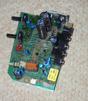
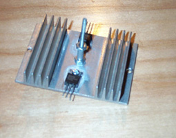
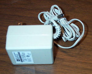 [The JBL amplifier comes in two pieces - the amplifier
PCB and the wall-wart transformer. The transformer is labeled
14 VAC @ 850 mA, 18W. The TDA7360 package and a TO-220 package
sit on the top edge and are attached a heatsink that wraps
around to cover the entire back of the PCB.]
[The JBL amplifier comes in two pieces - the amplifier
PCB and the wall-wart transformer. The transformer is labeled
14 VAC @ 850 mA, 18W. The TDA7360 package and a TO-220 package
sit on the top edge and are attached a heatsink that wraps
around to cover the entire back of the PCB.]
It's not
too hard to figure out that this amplifier was originally
used in a multimedia speaker system. The PC board was mounted
in the right channel speaker where it received a stereo signal
from a PC sound card. There is an output to the left channel
speaker. This is a pretty standard design.
There are
5 connectors in the rear edge of the PCB - power supply in,
left speaker out, stereo in and two no-connection jacks. I
don't now what the latter jacks are for, nor did I bother
to trace the PCB layout to see if they have any real use.
On the front are a bass tone control knob, and volume knob
and an on/off push-button switch. The right channel output
is near the bottom of the PCB.
The amplifier
is based on a TDA7360 stereo audio amp "chip". By
itself, it offers a fixed gain of 20 dB with an input supply
range from 8 to 18 VDC. A
PDF spec sheet can be found here. SGS-Thomson calls this
a 22 watt part but this is the sum of both channels. With
a 14.4 V supply, the TDA3760 is rated at 12 watts into 1.6
ohms, 11 watts into 2 ohms, 8 watts into 3.2 ohms and 6.5
watts into 4 ohms; all per channel. This isn't much especially
at "real" impedance levels, but since my goal wasn't
to blow the house down, this would do. The TDA7360 is bridgeable
(though this PCB has no support for it) and I looked briefly
at using two amp boards, each bridged for more output. But
I eventually decided to run with just one board since I didn't
have enough room in the case to mount two.
To interface
the amp board to the rest of the pieces, I made small patch
cables to get to the left and right channel outputs. The amp
PCB is mounted vertically via an L-bracket mounted into the
unit's heat sink. This required that I disassemble the heatsink
from the PCB but that proved to be very simple. The L-bracket
is mounted to a small piece wood which in turn is mounted
to the chassis.
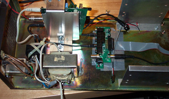
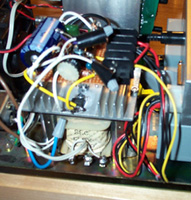
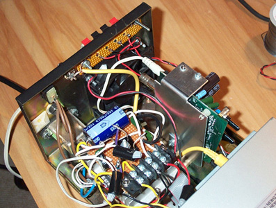
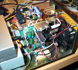 [This picture shows the final mounting of the amplifier.
A metal L-bracket is bolted to the heatsink behind the PCB
(not seen) and to the piece of wood on the case's bottom (the
cream colored piece in the picture). Two sets of red/black
wires go the terminal strip above the 80mm fan - these are
the left and right channel outputs.]
[This picture shows the final mounting of the amplifier.
A metal L-bracket is bolted to the heatsink behind the PCB
(not seen) and to the piece of wood on the case's bottom (the
cream colored piece in the picture). Two sets of red/black
wires go the terminal strip above the 80mm fan - these are
the left and right channel outputs.]
|
|
For power,
I ripped apart the wall-wart that came with the amp and strapped
it to the bottom of the case with two plastic cable ties.
|
|
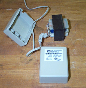
 [Inside the wall-wart transformer is an EI core. I drilled
four holes into the case and tied the core with two plastic
ties. I used electrical tape to keep the transformer contacts
from accidentally touching the case (or anything else for
that matter).]
[Inside the wall-wart transformer is an EI core. I drilled
four holes into the case and tied the core with two plastic
ties. I used electrical tape to keep the transformer contacts
from accidentally touching the case (or anything else for
that matter).]
|
The Power
Supply
The NewQ
3379 has no documented power consumption ratings anywhere
- not in the user's manual that came with the unit, nor on
their web site. The CD-ROM drive is rated +12V @ 1.2 A and
+5V @ 0.7 A. To determine my power needs, I dusted off a pair
of variable regulators I built years ago and hooked them up
to a 12.6 VAC @ 5A transformer. After verifying that everything
was working, I measured the total current draw with the CD-ROM
and NewQ 3379 connected. The +12V rail peaked at 1.2 A during
the initial motor spin-up and settled to under 0.5 A while
playing a CD. The +5V rail peaked at 0.4 A and settled to
a little more than 0.3 A.
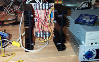 [This is my test power supply. There are two LM338 5A adjustable
regulators; one per heatsink. I used this setup to measure
the actual current draw (not including the 80mm fan added
later).]
[This is my test power supply. There are two LM338 5A adjustable
regulators; one per heatsink. I used this setup to measure
the actual current draw (not including the 80mm fan added
later).]
Looking
at my parts bin, I decided to use a LM7805 regulator for the
+5 V rail and a LM317 for the +12 V rail. I have an older
LM7812 but unlike the newer units that are rated at 1.5 A,
mine was only rated for 1 A. It probably would have worked
just fine since the 1.2 A current draw was for a very short
time but the 1.5A rated M317 was the safer choice. The LM317
is an adjustable positive regulator so I had to add a couple
of resistors to tune the output voltage. Ultimately, I tuned
the +12V rail to +12.09V and the +5 sat at +4.995; all well
within the 5% margins dictated by the
ATX
power supply specifications that computer I/O devices
are designed for.
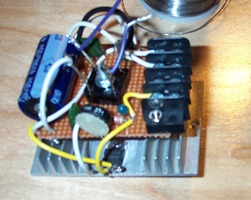
The power
supply is a triple decker affair. At the bottom is a 12.6
VAC 3A transformer from Radio Shack. Above this is a single
heat sink holding both voltage regulatorst. Both TO-220 regulators
are insulated from the heatsink. Above the heatsink is a small
board with the rest of the power supply parts - a 4700 uF
capacitor, a full-wave bridge rectifier, voltage control resistors
and some bypass caps. A terminal strip delivers the power
to the devices.
|
|
[The three layers of the power supply are the transformer,
the heatsink and the circuit board. The first picture shows
the Radio Shack transformer mounted to the case with two long
bolts. Behind the transformer is the back of the JBL amplifier
and the L-bracket that mounts it to the wood and case. The
heatsink has two TO-220 voltage regulators mounted on opposite
sides. The two bolts holding the transformer pass through
holes on the left and right edges of the heatsink. Aluminum
spacers supports the heatsink. In the middle of the heatsink
is another bolt. This one passes through the center of the
circuit board above heatsink. This bolt also holds the bridge
rectifier in place. The near side of the circuit board contains
a 10Kohm adjustment pot for the LM317. Final connections from
the transformer to the circuit board are made with wire nuts
so that they can be removed easily if necessary.]
To deliver
power to the CD-ROM and NewQ 3379, I used a cable from an
old defunct AT power supply. The four color coded wires are
wired to the termial block (red is +5, yellow is +12, black
is ground).
NewQ 3379
Platinum Tuner/Sound Processor
This unit
is entirely sealed. It comes with an I/O bracket that contains
a small PC board. This PCB and included cables re-routes signals
from a PC sound card back into the computer chassis and then
to the NewQ tuner/EQ via a ribbon cable. There is also an
antenna input. Refer to the NewQ web site for information
on the 3379.
I removed
the I/O bracket from the small PCB and mounted the PCB on
the bottom of the case, under the CD-ROM drive. I made a patch
cable to get the analog line-level output signal from the
CD-ROM drive to the NewQ I/O PCB
|
|
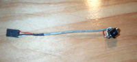
[I took a spare CD-ROM audio cable and connected it to
a 1/8 inch stereo male jack. This allowed me to connect the
output of the CD-ROM to the stereo input of the NewQ 3379
without destroying a stereo patch cable. I eventually used
electrial tape to loosely tape over the 1/8 inch jack to keep
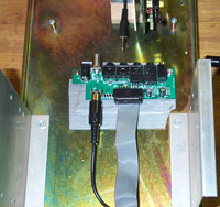
it from accidentally shorting out against the case. The I/O
PCB for the NewQ 3379 is bolted to the bottom of the case,
under the CD-ROM drive. Only the PCB is mounted; the I/O bracket
has been removed. From the front, you can see the space beneath
the CD-ROM drive. The ribbon cable connecting the I/O panel
and NewQ 3379 is visible. Holes in the metal at the bottom
of the picture are air intake vents.]
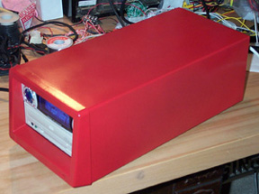
Final Touches
At the rear
of the housing, I added three more parts - a fan, a speaker
terminal strip, and an antenna jack. Finally, I spray painted
the housing with red enamel paint. Yes, the paint was also
"recycled" - it was left over from some other project
and was just sitting there on the shelf.
The fan
is an 80mm case fan consuming 0.15 A from the +12V supply.
This is a relatively slow, weak and quiet fan. The power supply
transformer delivers a little over 14 volts past the bridge
rectifier so under normal operating conditions, the main power
supply heatsink dissipates about 4 watts of heat. The JBL
amplifier add to this heat of course. To see if I needed a
fan, I played an entire CD (about 1 hour) at full volume and
opened up the case. Without the fan, everything was hot to
the touch. The top of the case itself was warm. With the fan
running, only the power supply heatsink was warm; the amplifier
was nice and cool and the airstream out the rear was cool.
Given the large difference in heat buildup, I decided to keep
the fan despite the added noise. Note that the case does not
have vents on its top. If it did, I would have avoided the
fan entirely and let convection cool the interior. The case
does have air intakes under the front bezel thus creating
a nice airflow path through the interior for the rear mounted
fan.
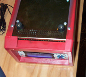 [The bottom front of the case has air inlets.]
The terminal
strip consists of four push-type spring-loaded connectors.
The case already had a cutout in the rear - it used to hold
a SCSI connector for the 8mm drive. I mounted the terminal
strip to a small perforated board and mounted that board through
the cutout. The antenna connector is just a panel-mount F-jack.
The NewQ 3379 has an RCA connector for an antenna signal and
comes with a wire antenna. I ripped apart an old RCA patch
cable and wired it between the F-jack and tuner. The rest
of the case had all the basic things I needed - 3-prong power
receptacle with EMI filter, fuse, and power switch (in the
rear unfortunately).
|
|
|
|
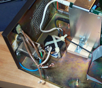
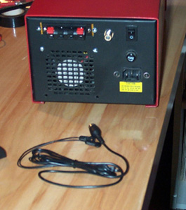
[The rear of the case shows the fan grill, the speaker
terminals, the antenna jack, power switch, fuse, and power
cord receptable. The antenna wire is in the foreground on
the benchtop. On the inside, we see the yellow antenna wire
and the red/black speaker outputs.]
Results
I must say
that I'm really happy with the results. The unit weighs a
ton and is rocks solid. The fan is a bit noisy when it's on
and not playing music, but put on some music and fan noise
vanishes. The only parts I had to buy were two TO-220 insulating
kits, a 4700 uF capacitor, the speaker terminal strip and
a panel mount F-jack, all from Radio Shack.
Future Mods ?
There are
a few obvious improvements I can make. The ones I have in
mind are :
- Drill
holes on the top of the case for ventilation and remove
the fan
- Replace
the JBL amp with an LM3886 (or similar) amp.
- Mount
a front panel power switch.
- Make
use of the digital out on the CD-ROM drive to avoid using
the unit's DAC.
Of course,
the amount of work involved with each mod varies and some
may not be worth the trouble. But that's way off my horizon
so I won't even think about them for now :)
|
|
05-October-2002
Note: The
contents in these pages are provided without any guarantee,
written or implied. Readers are free to use them at their
own risk, for personal use only. No commercial use is allowed
without prior written consent from the author.
|
|
 |