|
Another Analog Digital Clock (with temperature and humidity)
Almost as soon as I finished my first Analog Digital Clock, I started thinking about the next one. That first clock was started without a concrete plan; I didn't know what the final device would look like until I had collected enough material to make it viable. Upon completion of that clock I had a box full of leftover meters of varying sizes, shapes, styles and electrical requirements. I already have too much "stuff" (some would call it "junk") so my next clock would have to be made from existing meters - no more scavenging!
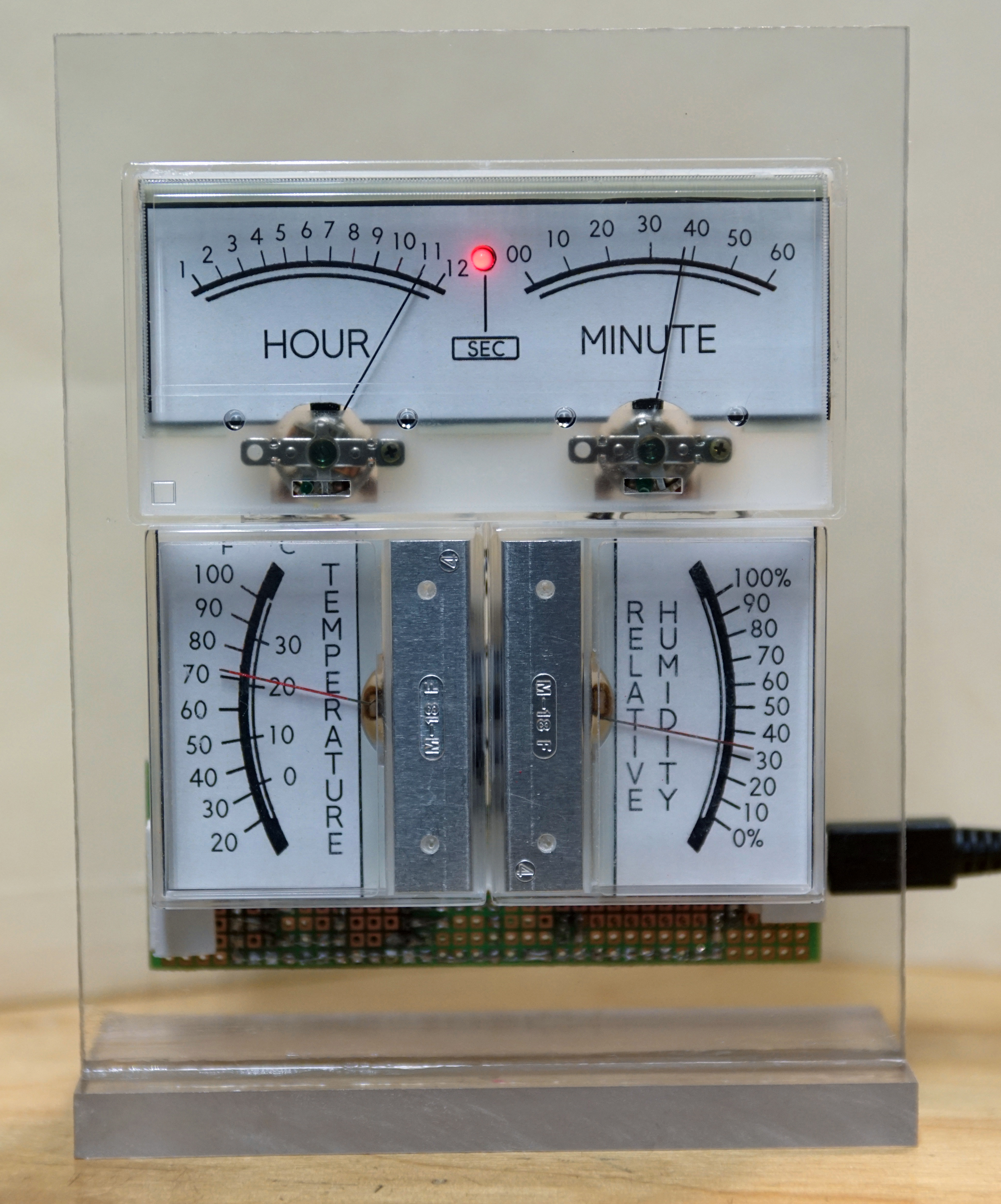
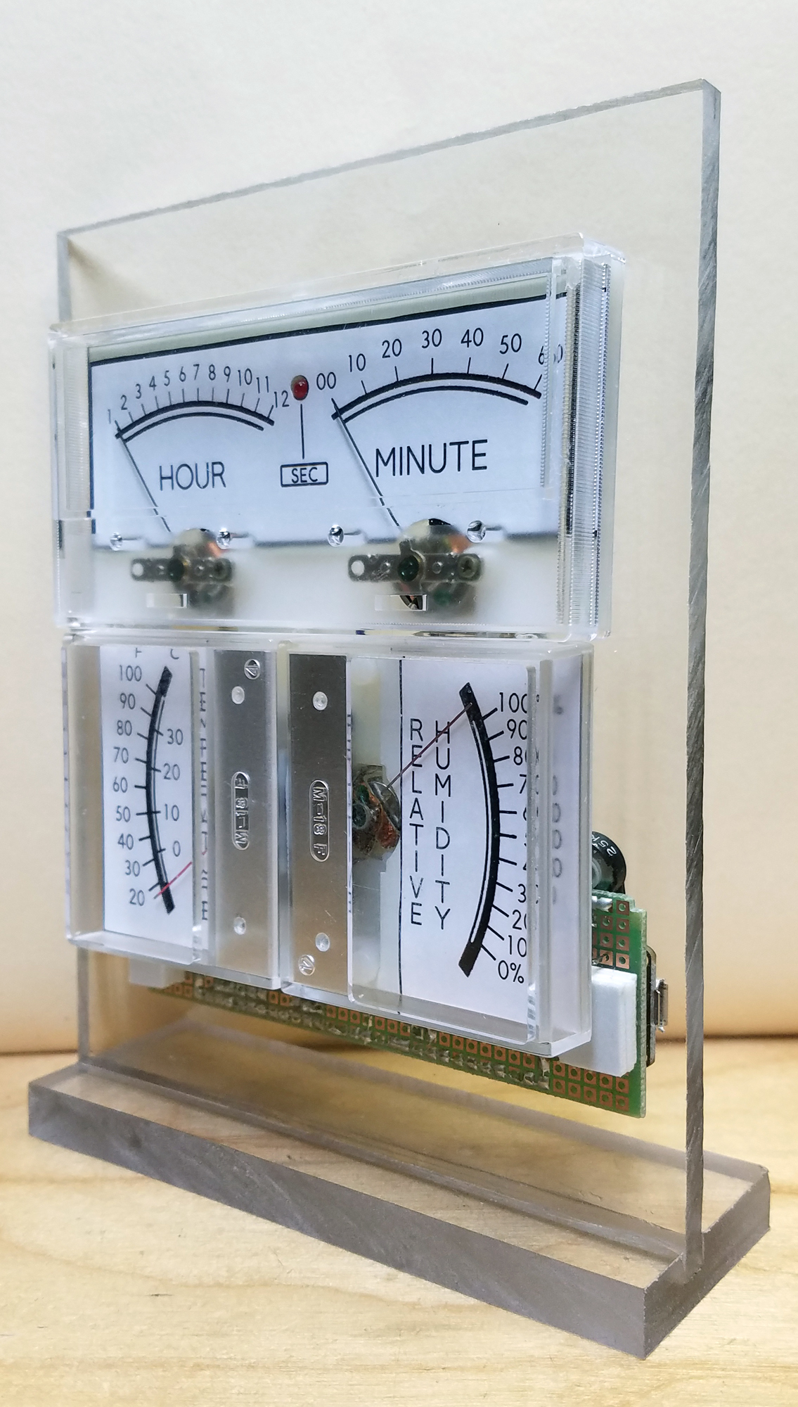
Fast forward 2+ years. It only took a few nights to finally get this done. Here are pictures of the clock:
The meters I've scavenged came from varying sources. Some are round antiques like the ones I used in my first clock. Others are simply old cheap multimeters - these are hard to repurpose because the meter mechanism is usually embedded into the plastic housing and can't be easily separated. There are also more modern meters with simple rectangular faces - these can still be bought new but are not cheap. Lastly there are VU meters recycled from old cassette tape decks.
There were other important factors in this design compared to the first clock:
- Lower cost.
- Simpler build.
- Different feature set.
- Smaller footprint.
- Packaging to match the materials used.
Before I started the design process, I wanted to know which meters in my collection could be used. For the older meters, I took time to clean and measure their response to input voltages. It turns out that almost all of my older meters required a relatively high operating voltages. Only the VU meters I had recycled from old tape decks could be easily used - they had an operating voltage well under 1V each to max out the meter. Apparently I lucked out with my choice of meters when I built the first clock.
Here's the final parts list and design.
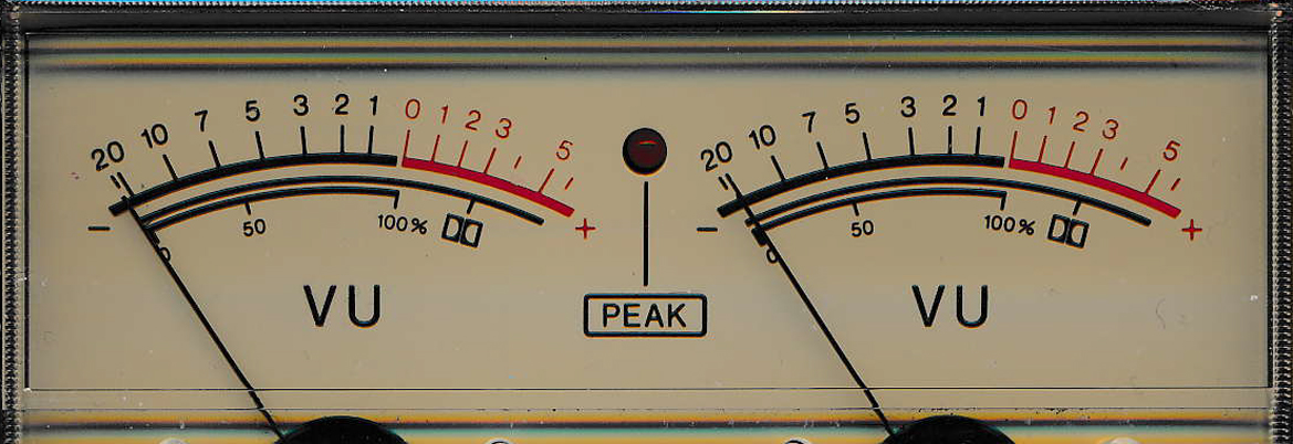
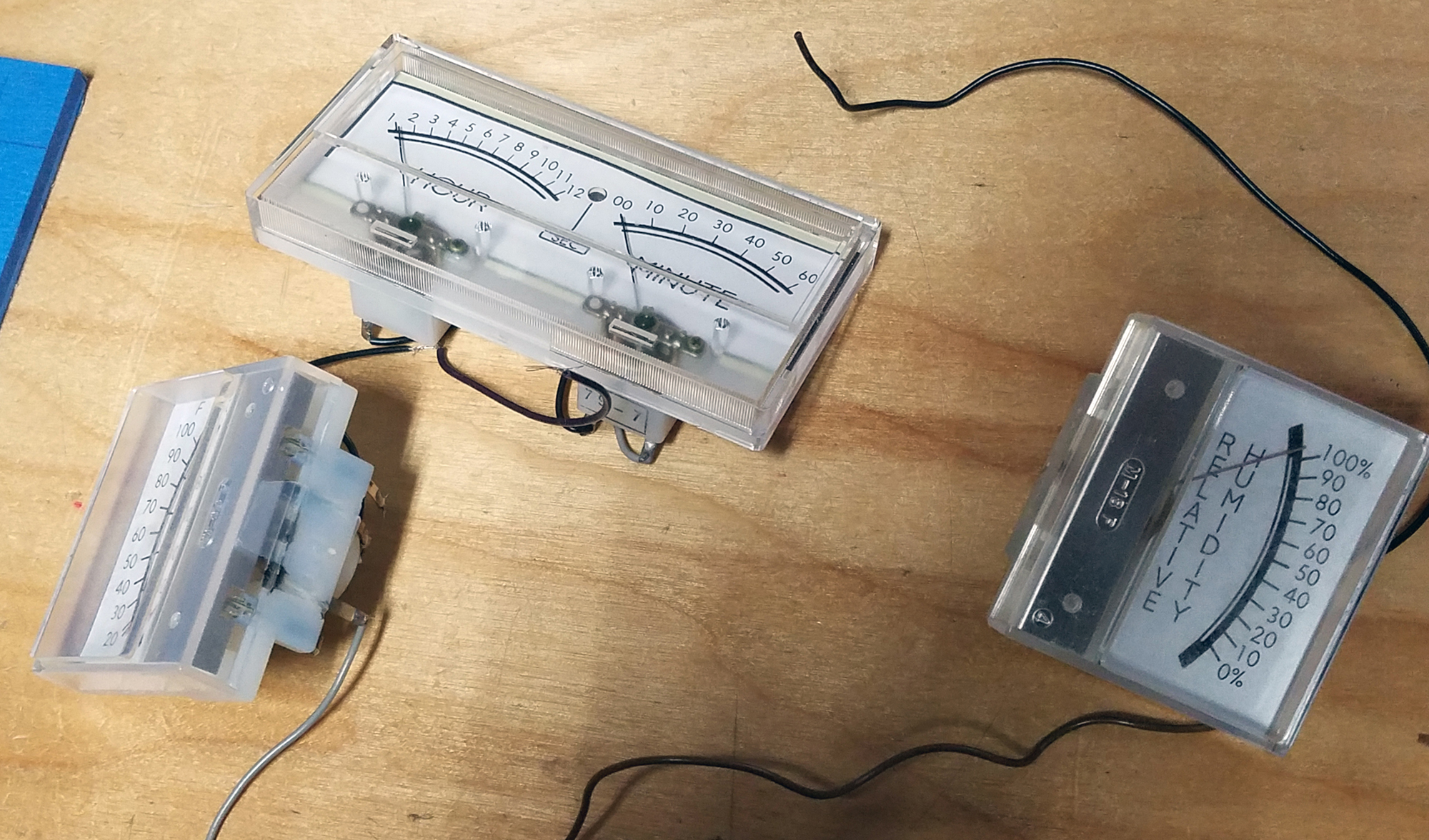
- There are 4 meters total - Hour, Minute, Temperature and Humdidity. I happened to have a dual meter (I think it came from an Aiwa 1260 Cassette deck) with an LED in the middle (to indicate audio clipping) so that became the Hour and Minute indicator. The LED would flash to indicate seconds. For temperature and humidity I used two other audio meters from an old tape deck but mounted these vertically - this was done for 3 reasons: it gave me more room to print numbers on the meter's face, it allowed me to better hide the cutout in the polycarbonate mount, and it looked better from a relative size perspective with the other meters. In other words, it's important to take all factors into account before committing to a final look and feel. The original meters are shown below.
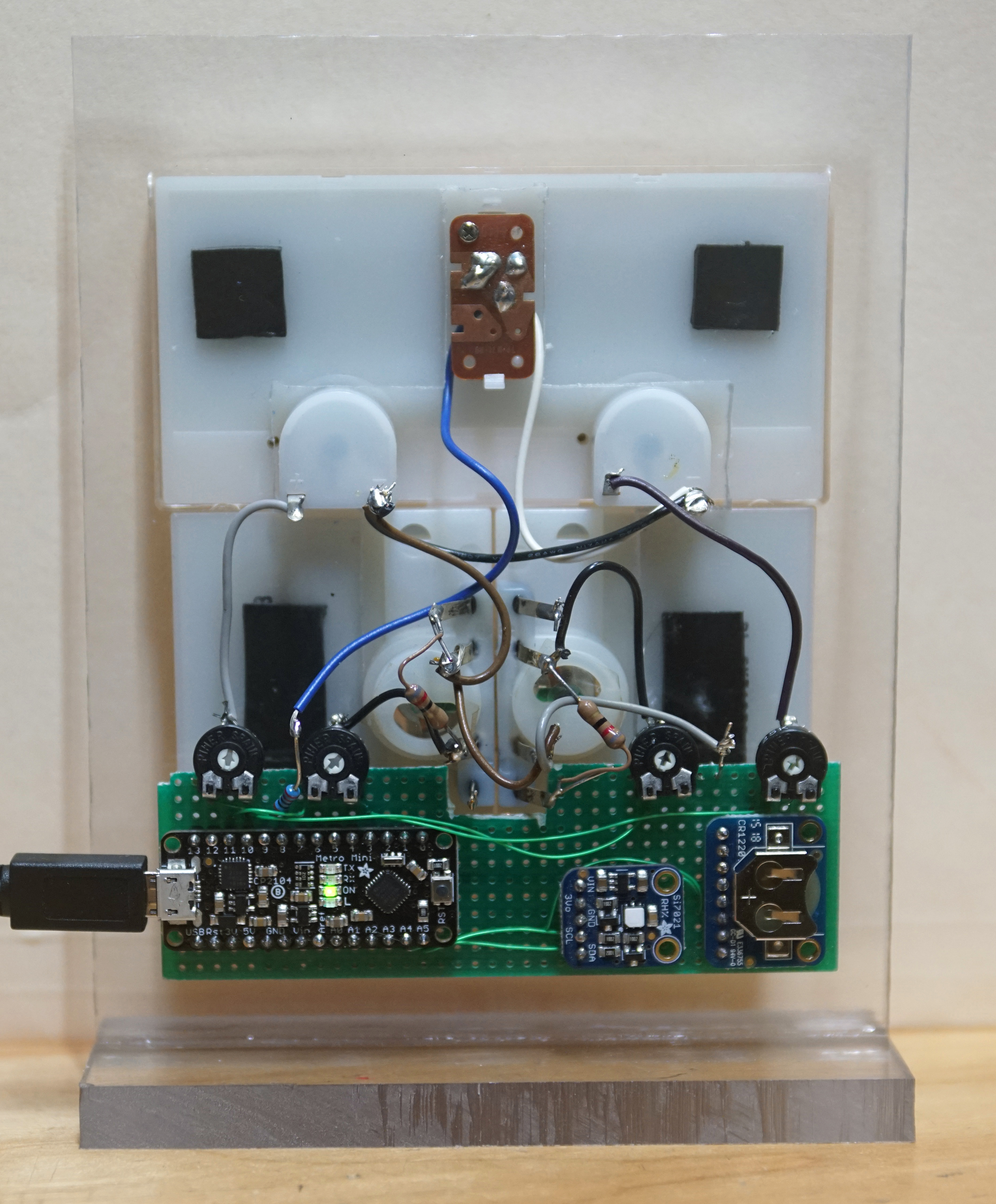
- The processor is now an Adafruit Metro Mini 328. This is essentially an Arduino Uno on a diet. It's small and cheap but has enough I/O for what I needed - I2C connectivity and 5 digital outputs. To drive the meters, I used the "analog" digital output. These are not true analog outputs (as would be the case if this arduino has a digital-to-analog converter or DAC). The analogWrite() function is actually sending a pulse-width-modulated (PWM) signal to the digital output pin. The pulse train is of high enough frequency that the meter averages out the high and low states into a steady voltage level. To maximize control of the meters, a 25Kohm potentiometer (pot) is connected between the digital output pin and the meter. Each pot is calibrated for its specific use (see below). Gone are the digital pots and op-amp from the first clock.
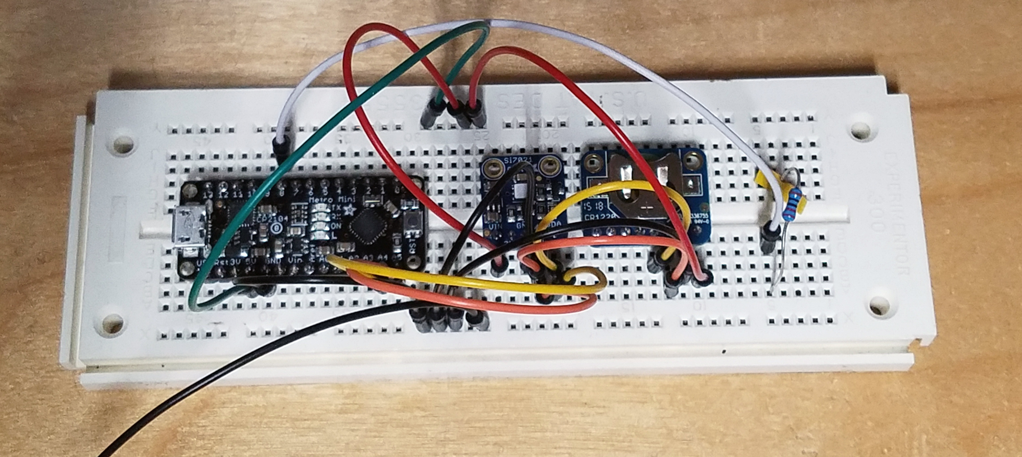
- I used the same RTC chip as in the first clock project but this time the DS3231 is in a breakout board form factor instead of a Feature Wing. For weather features I used an Si7012 breakout board. Both breakout boards connect to the Metro Mini via +5V(Vin), ground, SDA and SCL (the latter two form the I2C bus). Below are the three main components on a prototyping board. Notice the battery holder on the RTC on the right - this holds a CR1220 battery to keep time during power outages.
- Everything is mounted on a piece of clear polycarbonate measuring a 0.225 inches thick and is intended for desktop use. Clear polycarbonate matches the look of the meters. The open back allows the Si7012 sensor to be fully exposed to the ambiant air temperature and humidity, as well as allow for airflow. To get good readings, it's important not to place this device near a heat source.
Also important in any design is the list of features not implemented.
- Two of the VU meters have internal lights but since the other two did not, I opted to not use them. It's also possible to retrofit LEDs in all four meters in the future. Better yet would be to add an ambiant light sensor and light up the meters gradually as needed.
- It's possible to edge light the polycarbonate. I played with this a little bit but preferred the clean look of the existing panel where all sides are plain.
- Initial time setup still requires a USB cable to a computer. There's code that automatically adjusts for Daylight Savings Time so the setup process includes entering the date. If this feature is scrubbed, it's possible to just have buttons to adjust the hours and minutes for the initial setup.
- It would be nice to have some sort of timer or alarm feature but the user interface would have to be easy to use.
Because I'm working with repurposed parts (meters) there's a distinct order to the build process.
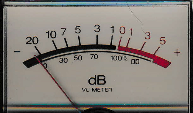
- Make a new face for the meters. This is a critical first step. To properly display values on the meter I need to program the correct PWM output on each digital output pin. And to do that I need to calibrate the pot attached to that pin. And to do that I need to have markings for the min and max values on the faceplate of the meter. All meters can be disassembled, but some are more difficult to work with than others. VU meters are usually held together with just clear tape on the sides. The face on my meters were glued in place so I didn't want to take any risks damaging the meter (the needle on these meters are delicate and easy to damage so be very careful when working with the meter open). I placed the meter in my scanner and imported the image of the face into Photoshop where I edited it for my needs. I then printed the result onto paper and used double sided tape to mount it over the old face. Now I know where the needles need to go from min to max. For humidity I picked a the full range from 0% to 100% though realistically I'll never use this range. Note that the Si7012 sensor is most accurace in the range from 20% to 80%. For temperature I picked 20F to 100F. Note that the face includes a celcius scale that is also centered to keep things visually balanced. Below are the finished meters with their new faces. And for the record, the Minute hand never reaches "60" !
- Calibrate the pots. Technically the pots are optional, but practically they are required. Each PWM digital output has an output that ranges from 0V to 5V (actually 4.92V on my board) and there are only 256 unique values that can be set. A setting of 0 will give 0V and 255 will yield the max 4.92V on my Metro Mini. The meters require a much lower voltage (on the order of 0.5V) to peg the output to their max. If I ran the meters without a pot and I only had 0.5V to work with, and assuming the meter is linear (which they are not) I would have just 0.5V (usable range) / 5V (output range) * 256 (number of programmable values) = 25.6 unique values to set. That's only 1/4 of the number I would need to set humidity from 0 to 100. It's not enough to set 60 minutes or 80 different temperatures. It is fair to point out that with these meters, fine grain detail is not important but a pot is easy to use so why not use one? Each pot is just a voltage divider where the digital output is connected to one end of the 25Kohm pot, ground is attached to the other end and the wiper is connected to the meter. To calibrate, use your software to output 255 to the desired pin, then turn the pot until the needle is over the max tick mark on the face of the meter. Each pot is different so do this for each one seperately.
- Calibrate your software for each major tick mark.There are different ways to select the actual PWM value sent to the meter. If the meters are linear, you just need to know the min (calibrate with PWM=0) and max (already set to 255 from the above pot calibration) and interpolate inbetween those two values. My meters were not linear (far from it) so that left two options - a lookup table or a mixture of interpolation and lookups. I did the latter because I was too lazy to calibrate each temperature, minute and humidity values. Besides I only had tick marks for increments of 10 in 3 of the 4 meters so calibrating them at a finer level of detail wasn't worth the effort. So I calibrated in increments of 10 (degrees, % humidity, minutes) and interpolated for values inbetween. It worked out rather well.
- Add a resistor for the LED. The LED that flashes seconds is connected to a digital output. I used a 220 ohm resistor in series with the LED.
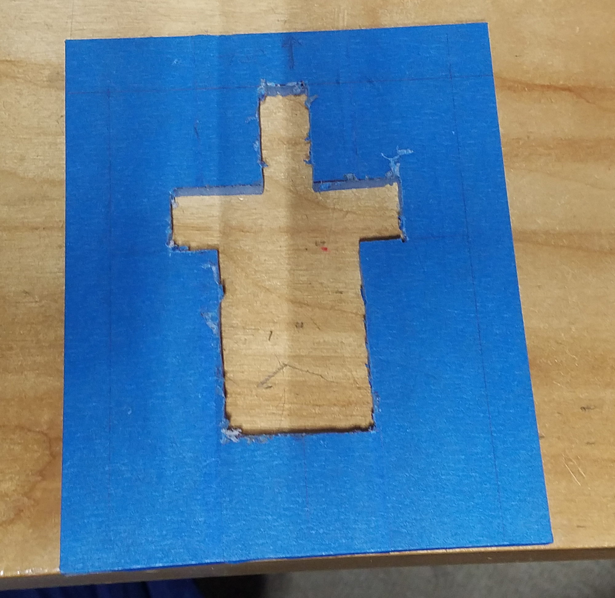
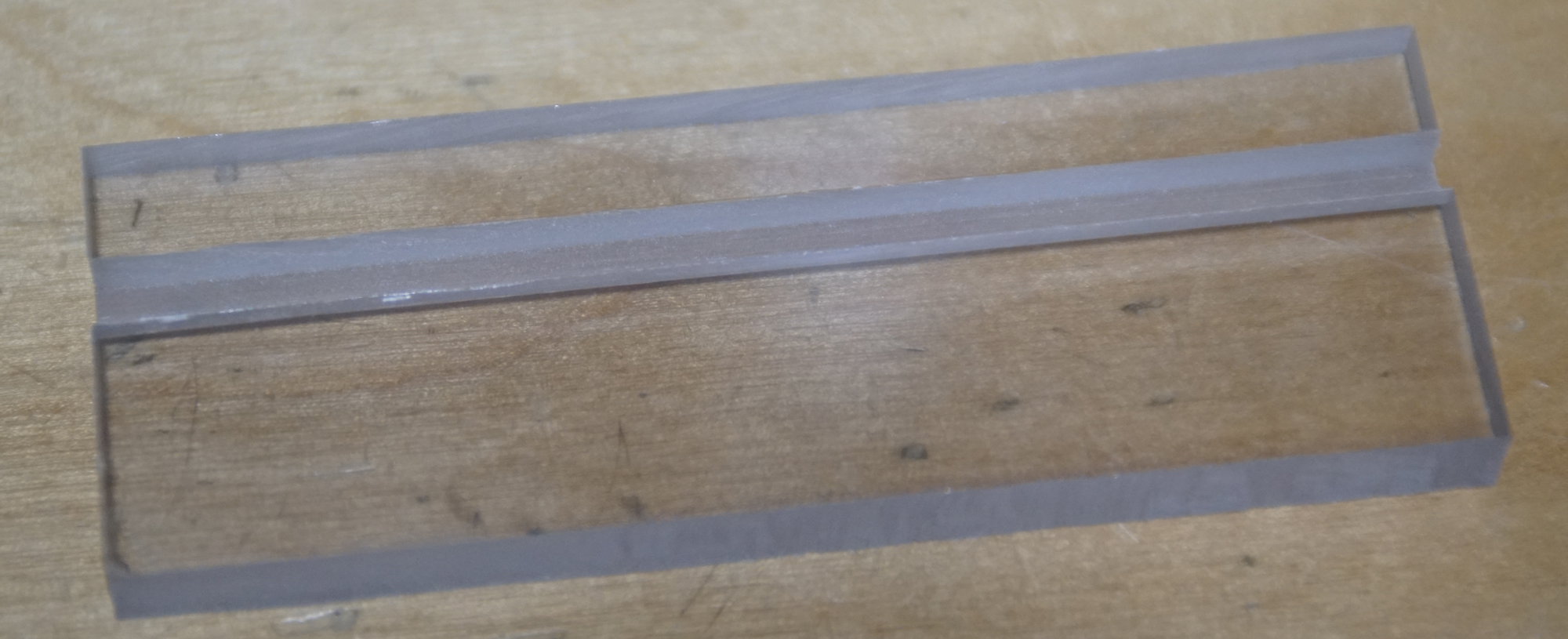
- Cut polycarbonate. I used blue masking tape to protect and give me a writing surface on the polycarbonate. A drill and jigsaw is all I used to cut out holes for the meters to sit in. The bottom piece of polycarbonate is dadoed on a table saw. The two pieces of polycarbonate are glued with Devcon clear epoxy.
- Assemble the components onto the polycarbonate using double sided sticky foam. The foam adhesive is much easier to use than nuts, bolts, screws, what have you.
The clock is nothing without some software. And this software is pretty simple stuff. It's mostly ripped off my first clock. Adafruit has support libraries for both the DS3231 RTC and Si7012 weather sensor; the examples contain all that's needed to read and write the RTC, and read the sensor. The main loop just reads time and sensor information 10 times a second and updates the PWM output when the values change. The seconds LED flashes on for one second, then off for another second. Initiall setup for the clock is still over the serial port (meaning a computer is attached). This includes setting the full date (day/month/year) and is done because there is built-in daylight savings adjustment based on the date.
Still to be done - the Metro Mini is mounted horizontally to give room for a microUSB power cord. But the length of most microUSB connector heads tends to be large and somewhat unsightly. A simple solution is to get a right-angle USB cable.
|