|
Matrix Clock
Many years ago I got an anniversary clock. I don't recall where it came from but it wasn't anything
fancy - just a typical battery operated quartz clock at the top and a rotating figurine at the bottom.
After a few years, the bottom portion stopped working leaving just the clock ticking away. And then
the clock stopped as well. And I've always thought those cheap quarts clocks lasted forever!
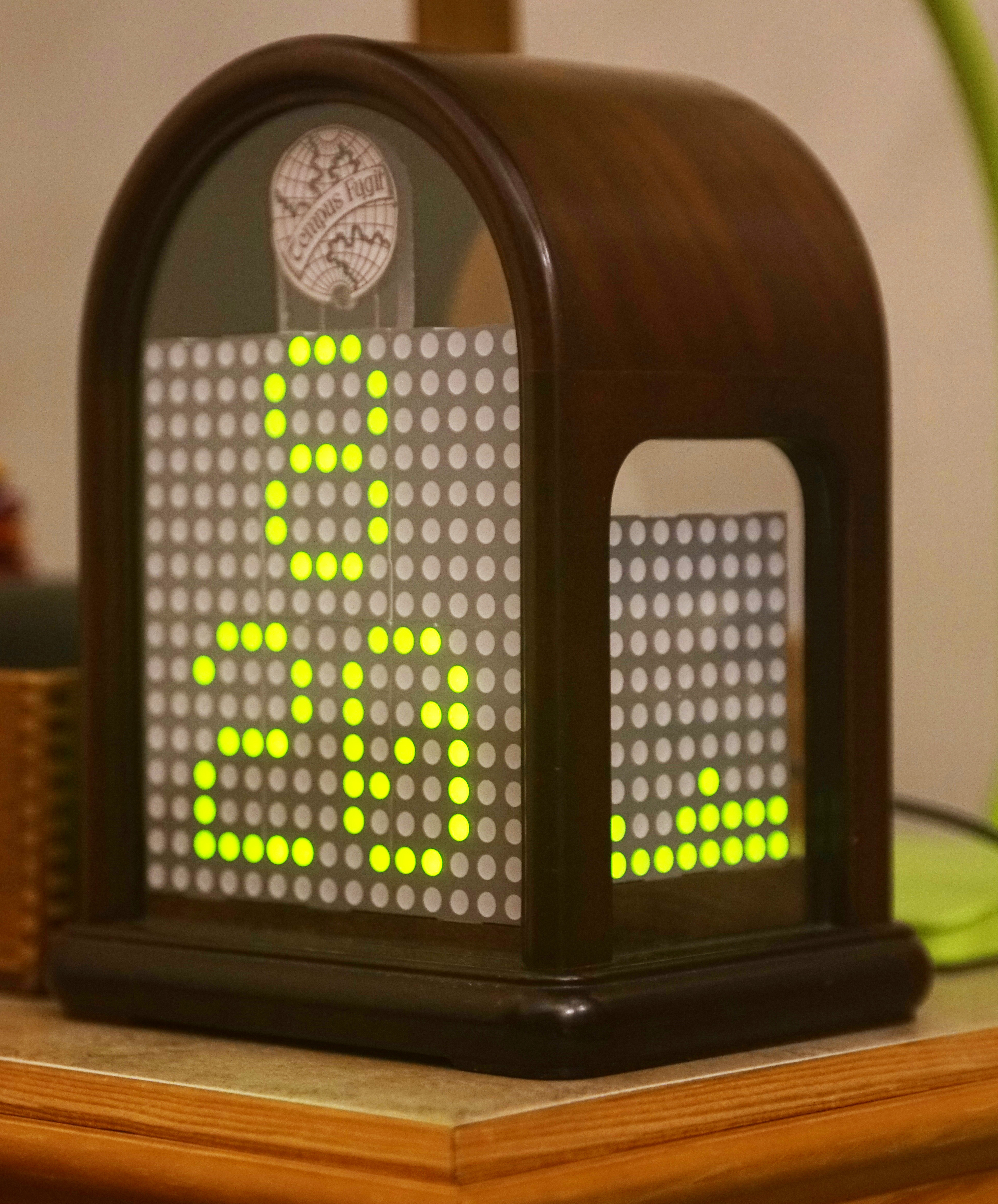
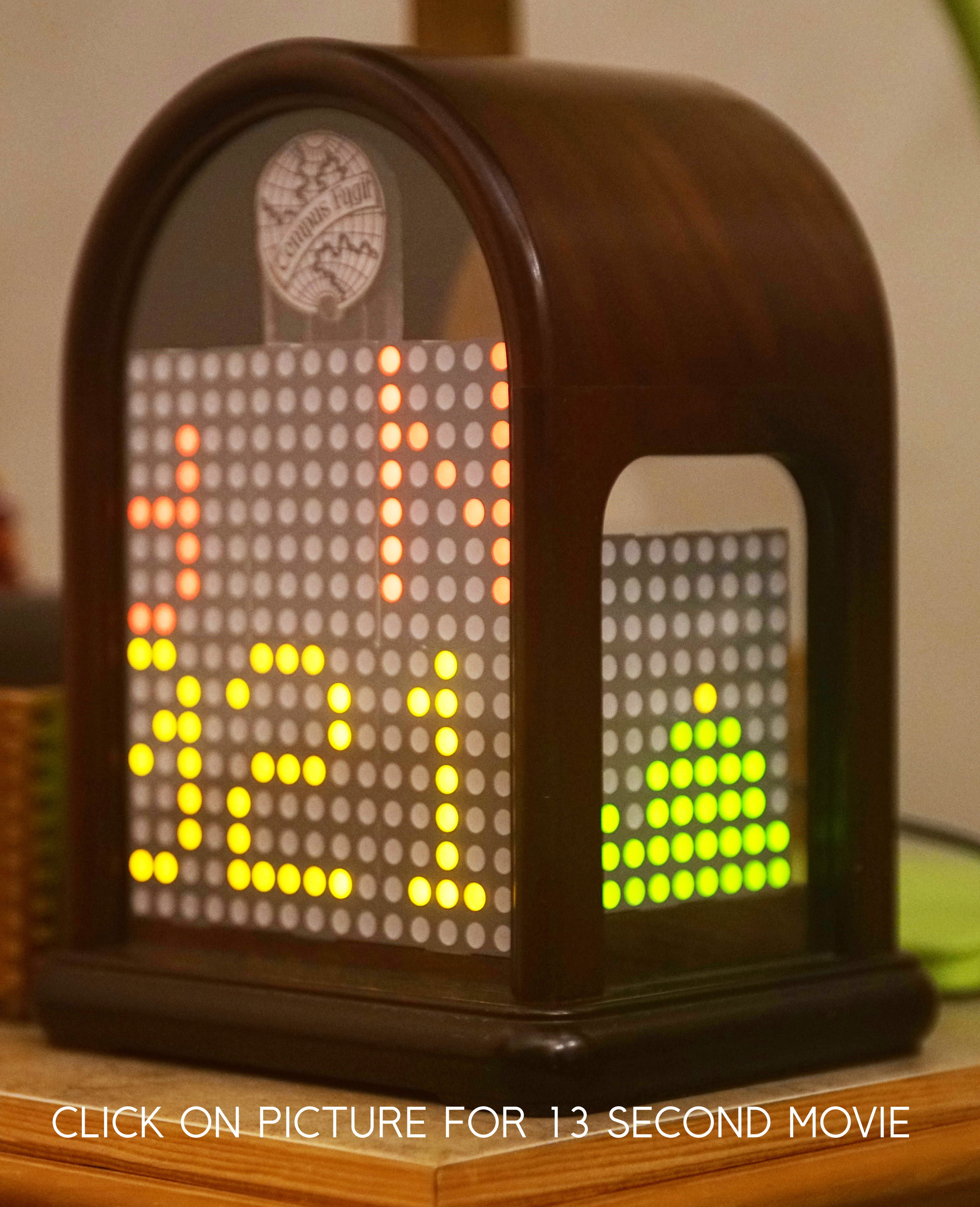
Above is a view of the time display on the left, and the scrolling message display on the right.
CLICK ON THE RIGHT IMAGE FOR A 13 SECOND MOVIE OF SHOWING THE CLOCK IN ACTION.
The message says "Happy New Year" in red on the upper part and "2021" in yellow on the lower part.
Below is the empty case.
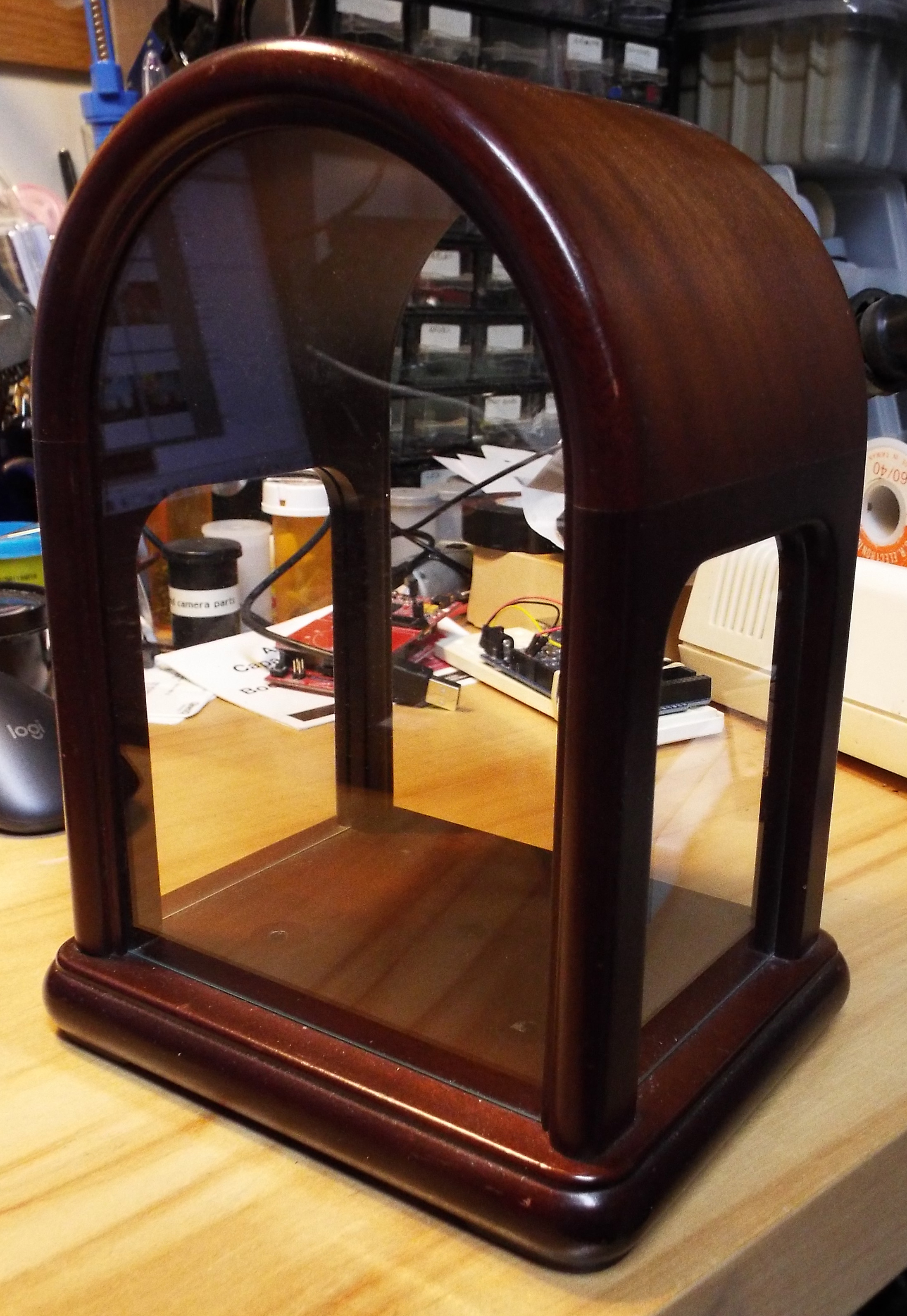
I like the overall form of the anniversary clock so I gutted the clock and looked for a new project
to stuff into its shell. It so happens that I had previouly bought 40 5x8 LED matrix displays panels for
a different project that went nowhere. Today you can get much more useful
programmable RGB arrays but I already had these so I forged ahead and stuffed the matrices
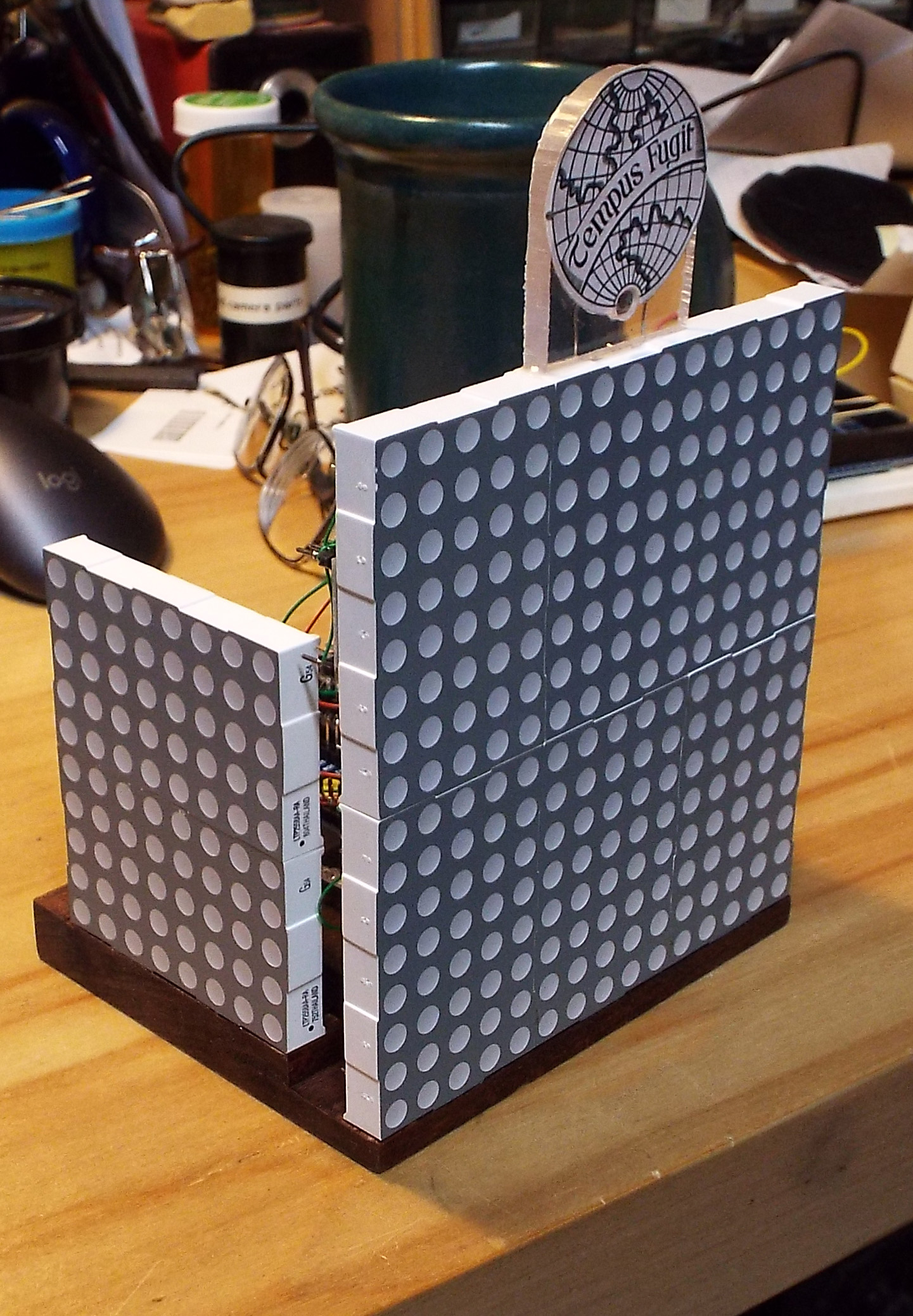
into the anniversary clock case. They fit amazingly well. On the front face, six of them fit in
two rows of three panels for an effective 16 pixel rows by 15 pixels columns.
For each of the sides, I could only fit 2 panels.
I went with the 10 pixel row by 8 pixel column layout because it allowed me to more easily assemble everything
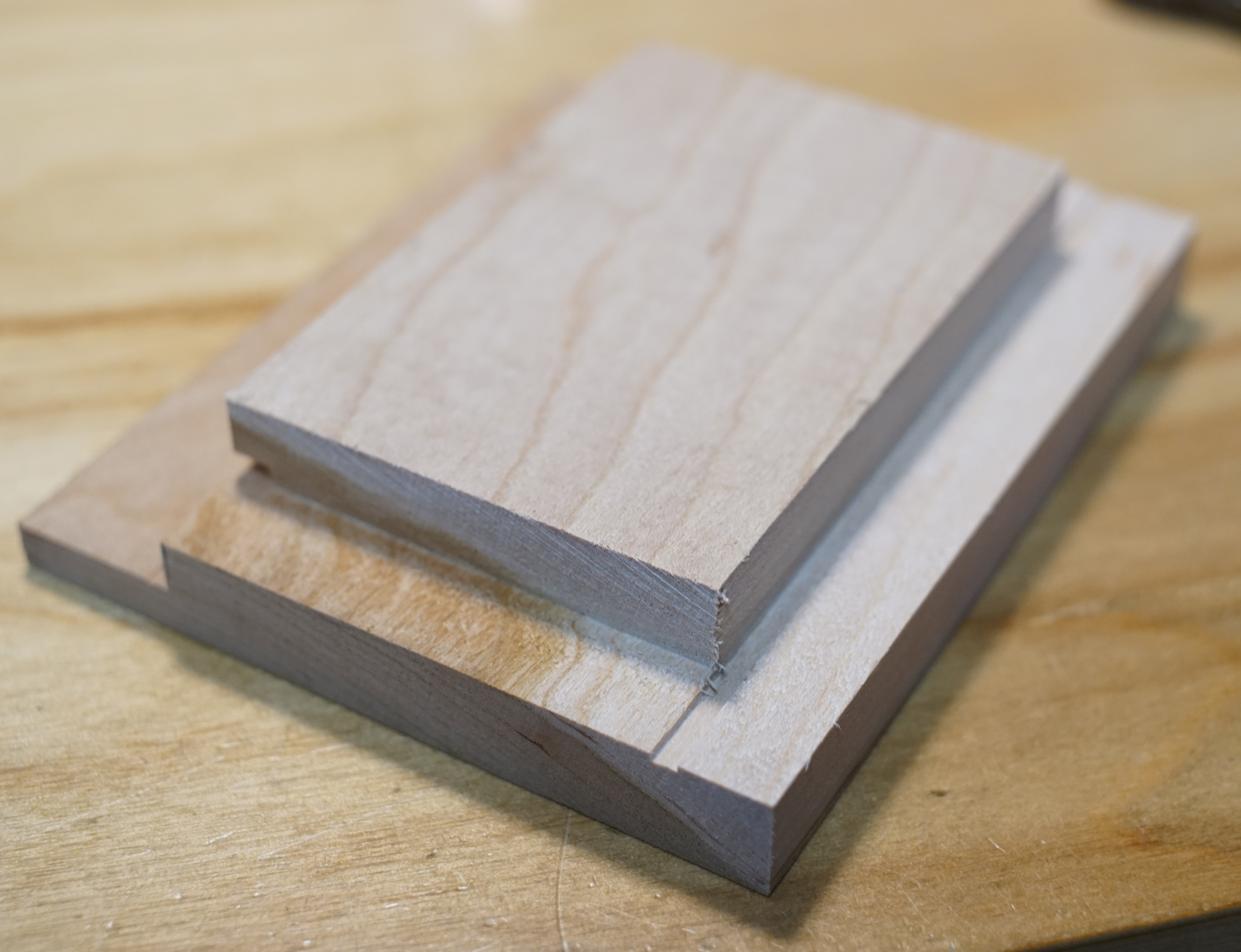
outside the case and slide it in via the back. Below are the front and rear of the LiteOn panel
as well as a view of the assembled left and center panel.
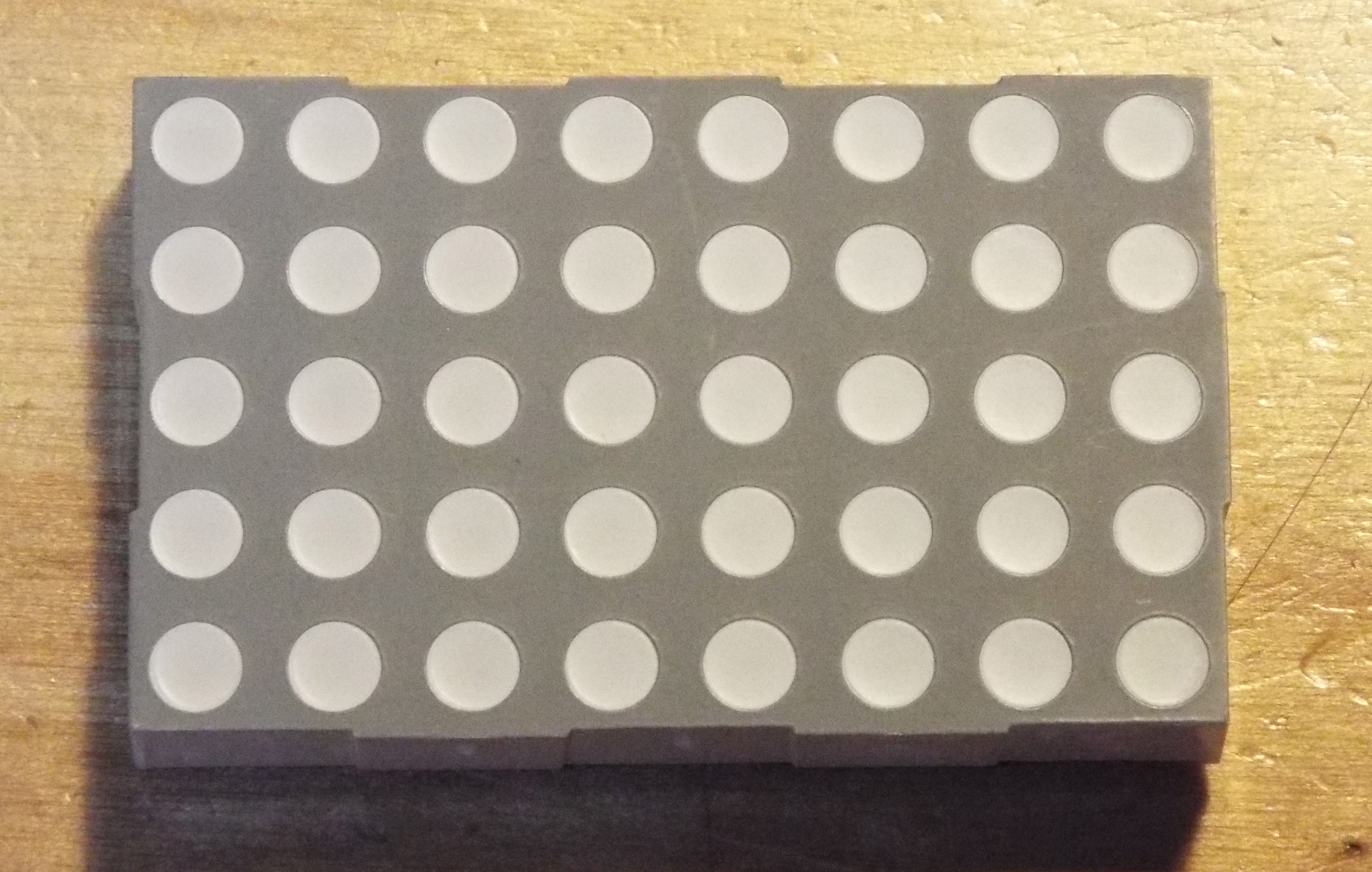

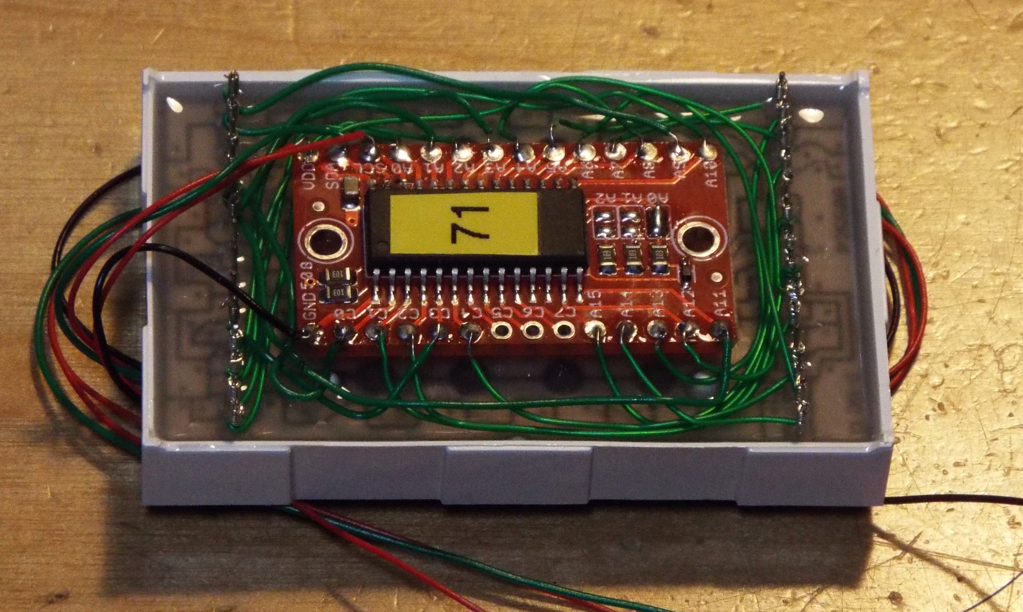
The LiteOn 5x8 Matrix Display consists of 40 pixels arranged in a 5x8 grid. Each pixel has a red
and green LED so there are 3 possible colors - red, green and yellow (or closer to orange). From a
hardware interface point of view, the LEDs are wired in a row/column matrix, one for the red and
one for the green LED. I used one HT16K33 controller for each display panel whichs communicates
over an I2C interface. If I had been reasonable, I would have made a PCB for the
controller and display and made my life simpler. But of course I had to do things the hard
way so I wire wrapped each controller to the display by hand. Perseverance. Or Stupidity.
Take your pick. Below is a single unit (3rd batch, second controller board) and the
six controller unit glued up (1st and 2nd batch, first controller board). The wiring varies
with each batch as I updated the way I made them.
To talk to the HT16K33, I created a "LiteOn_Bicolor_5x8" class derived from the Adafruit_GFX class.
This lets me leverage the Adafruit graphics library to write and paint to the panels. Each panel
is actually treated as an independent display with different offsset for X and Y coordinates located
within a large virtual 2-dimensional space. Writing
a character to the entire panel is really writing to each panel with the same data but different offsets.
The library actually stores all updates in memory and only updates the hardware on request.
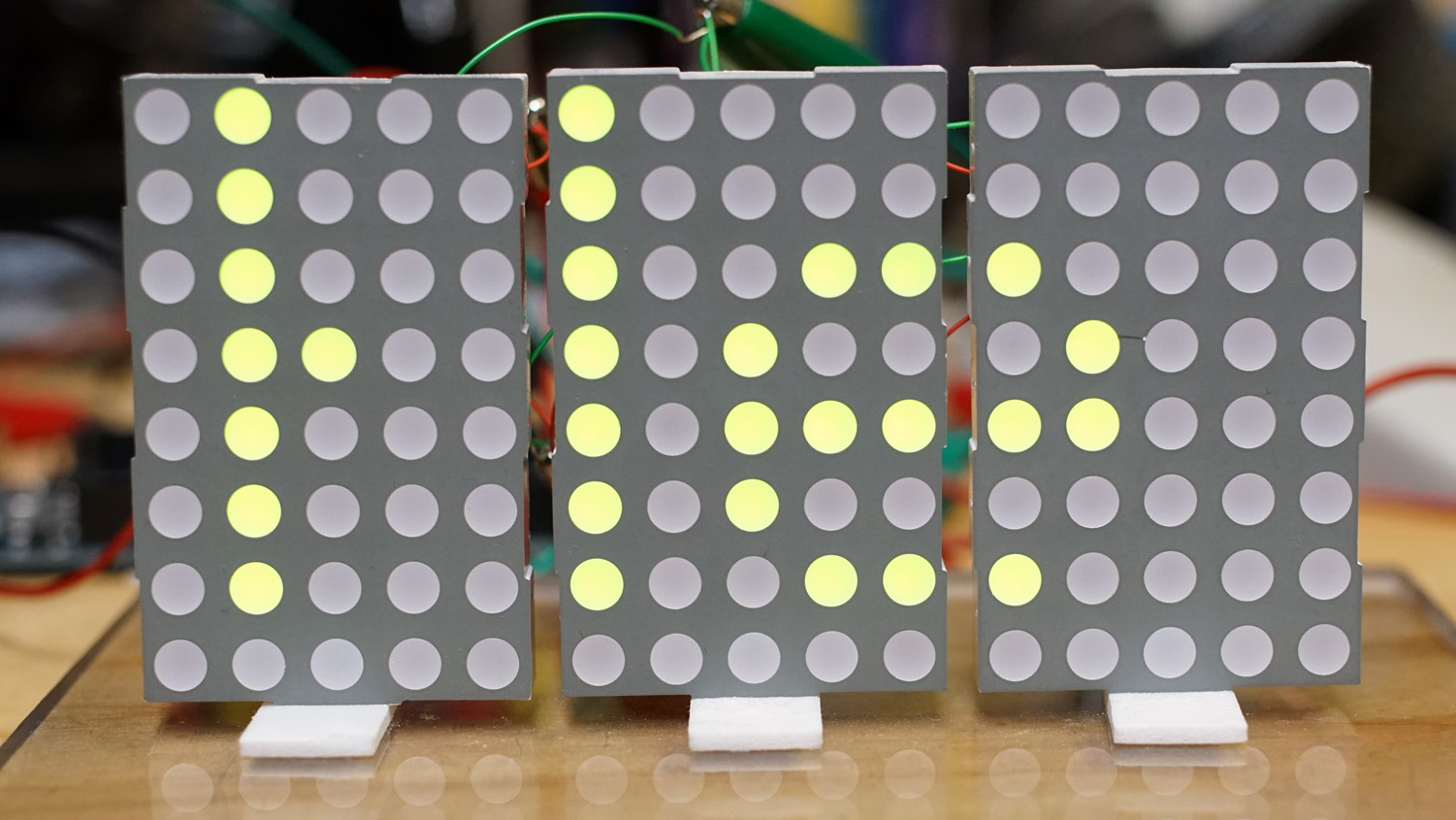
This could be better optimized but for now, it works and does the job. Below we see three panels
during software debug. The letter 'H' spans two panels but seems incomplete because the camera's shutter
was fast enough to catch some of the LEDs in their "off" state as they are multiplexed by the controller.
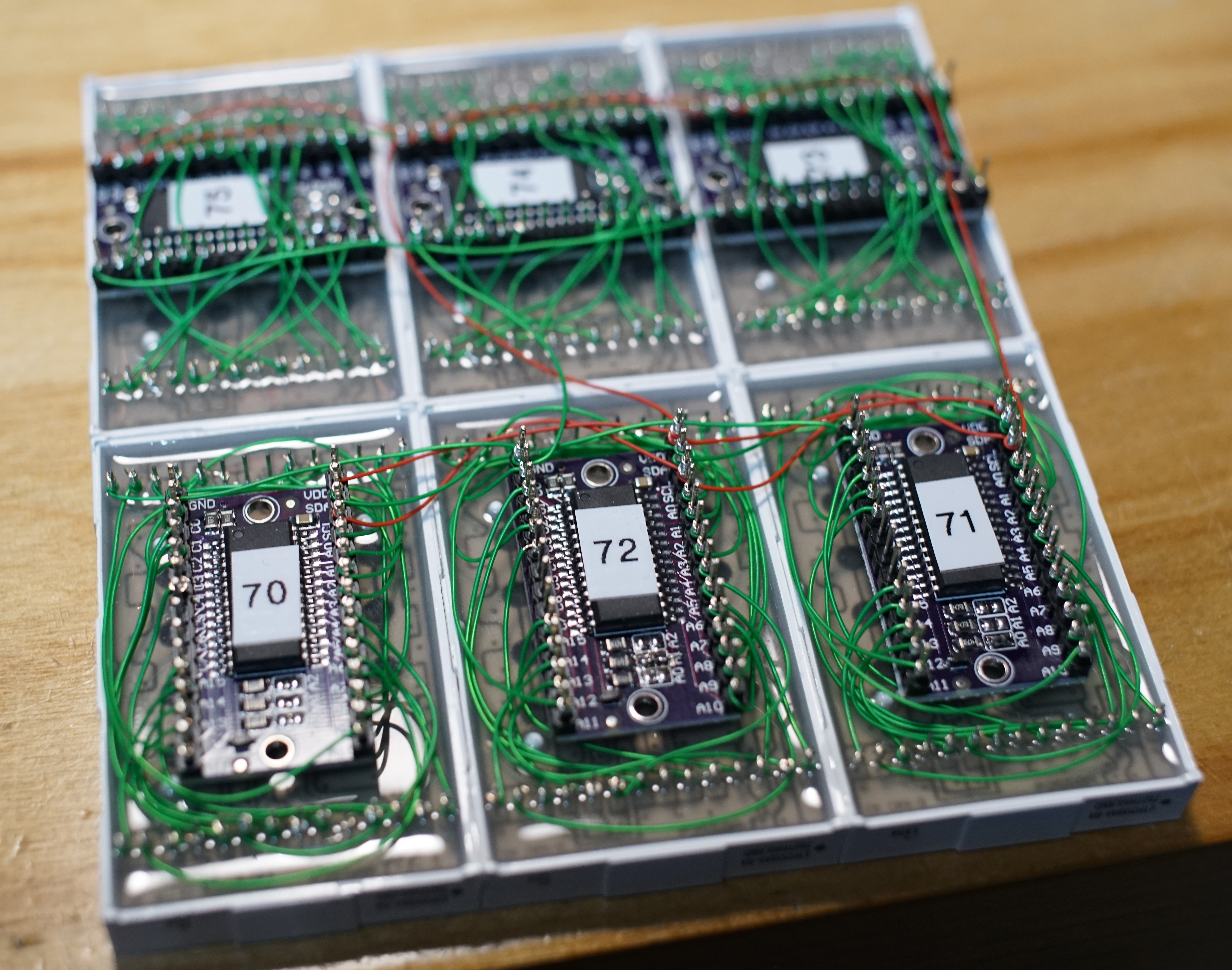
There are a total of 10 panels. Each HT16K33 can be hardwired to one of eight I2C addresses (0x70 to 0x77)
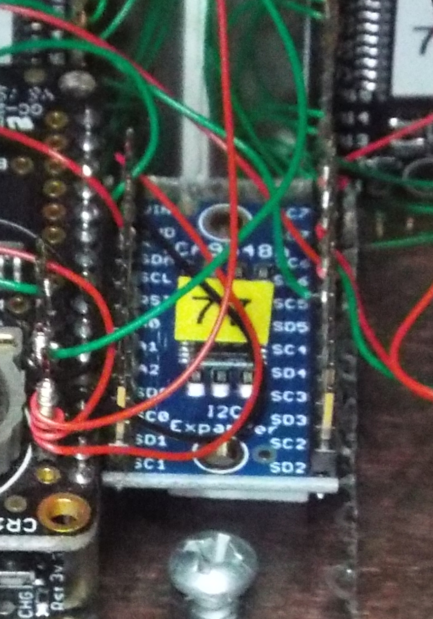
so I don't have enough addressing space to work with. Enter the LCA9548A I2C multiplexer.
This chip sits at I2C address 0x70 and routes control to one of eight I2C ports (0 to 7). So with the
multiplexer (via an Adafruit carrier board, product ID 2717) in place my displays are now
partitioned address ranges with two on the left,
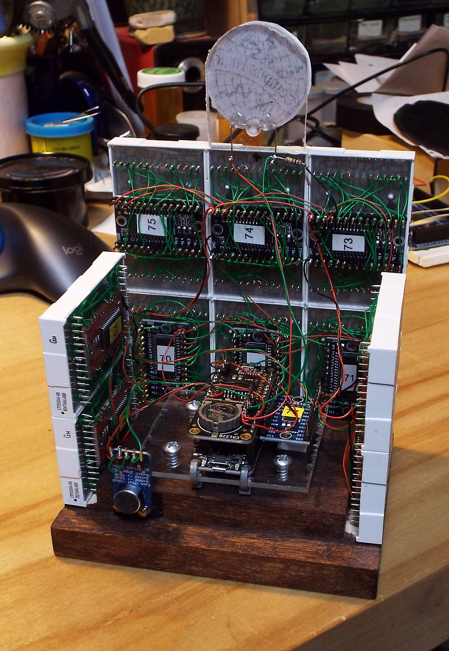
six in the center and two on the right. The picture below shows the multiplexer board to the right of
the Feather stack.
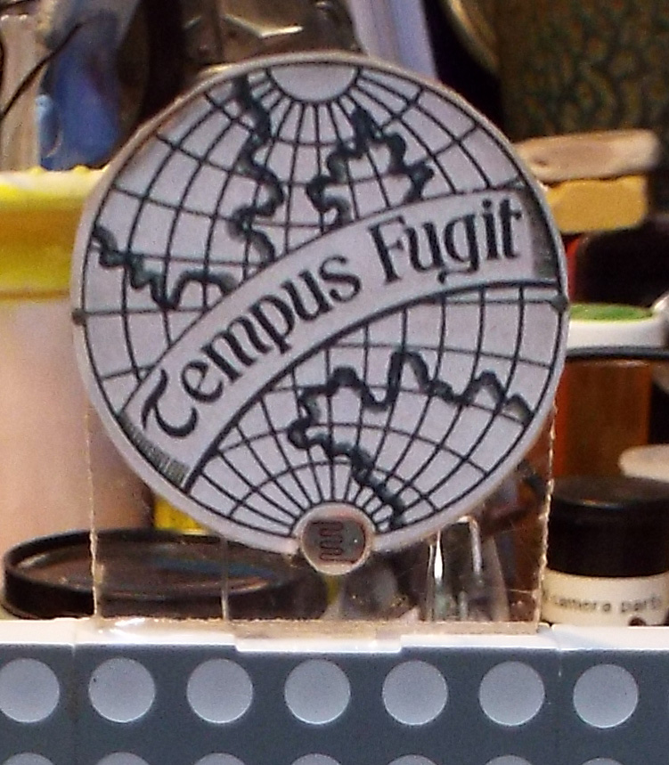
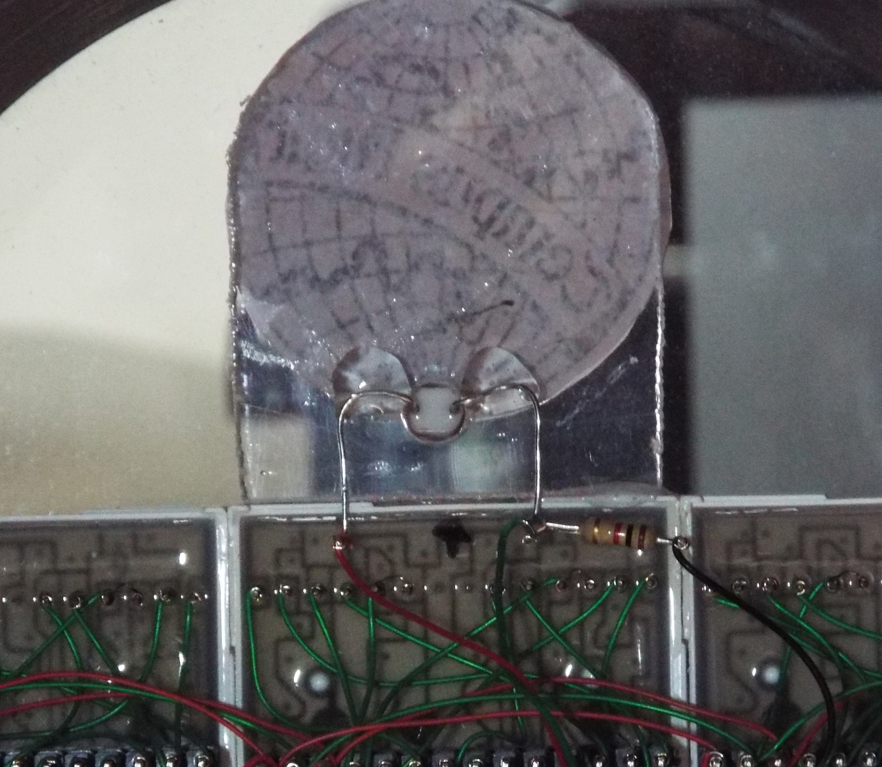
The HT16K33 controllers drives each LED from its internal pixel memory. By varying the
update rate, it can control the overall brightness of the panel. There are 16 levels
of overall brightness. To select the brightness a Cadmimum Sulfide (CdS) photocell is mounted
in a Tempus Fugit decorative piece epoxied to the top of the main display.
Combined with a 1K resistor, this presents a
voltage to analog input 0. This is sampled regularly in the loop() function to change
the panel brightness. The brighter the ambient light, the brighter the display.
The pictures below show the CdS cell (with the snaking line) and the connections
at the rear. The 1K resistor is to the right and the white blobs are clear epoxy.
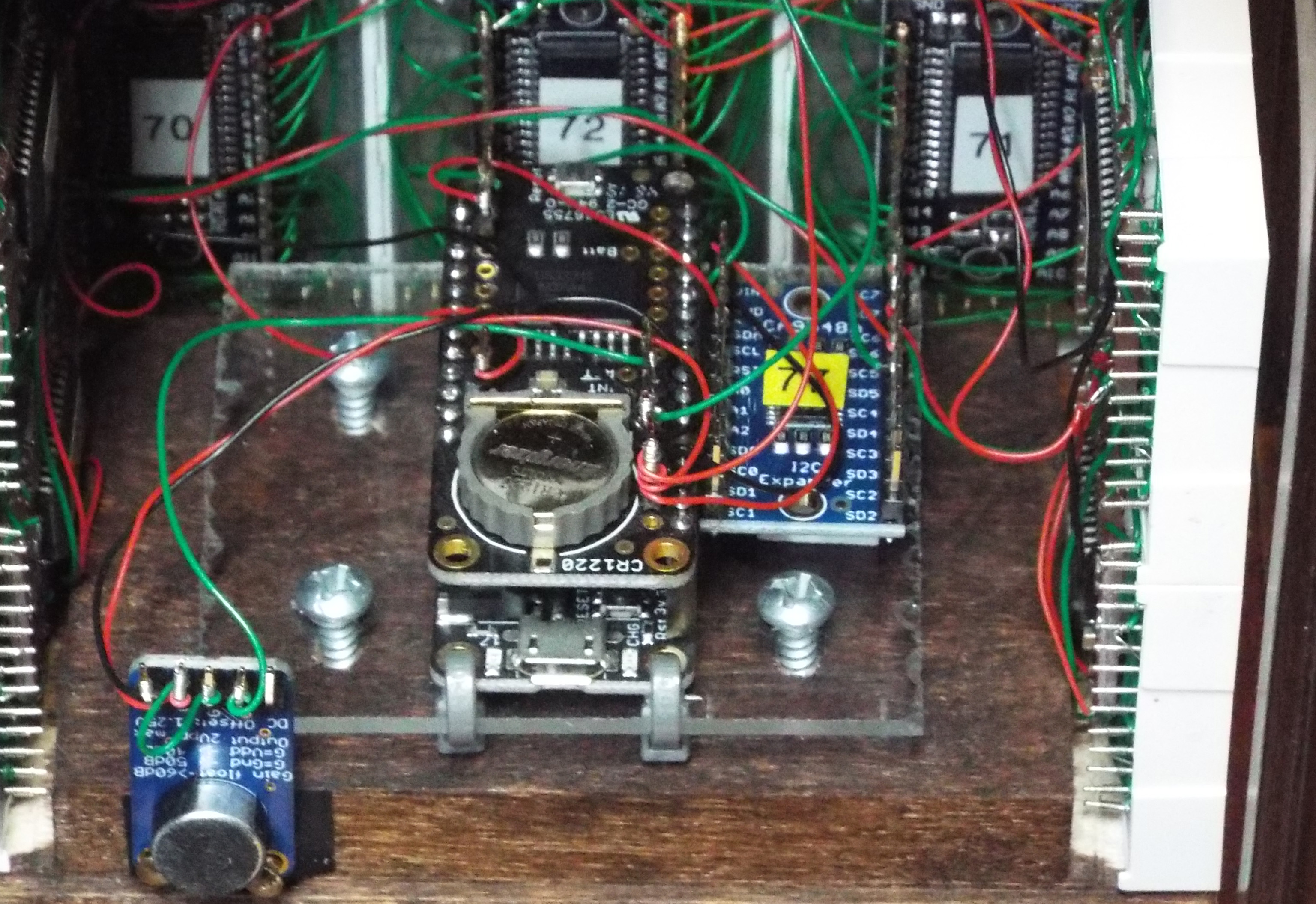
The clock is controlled by the same DS3231 precision chip I used in my other digital clocks.
In fact the code to control it is nearly identical. It performs daylight savings time
correction via a hardcoded table good for the next 10 years and has battery backup
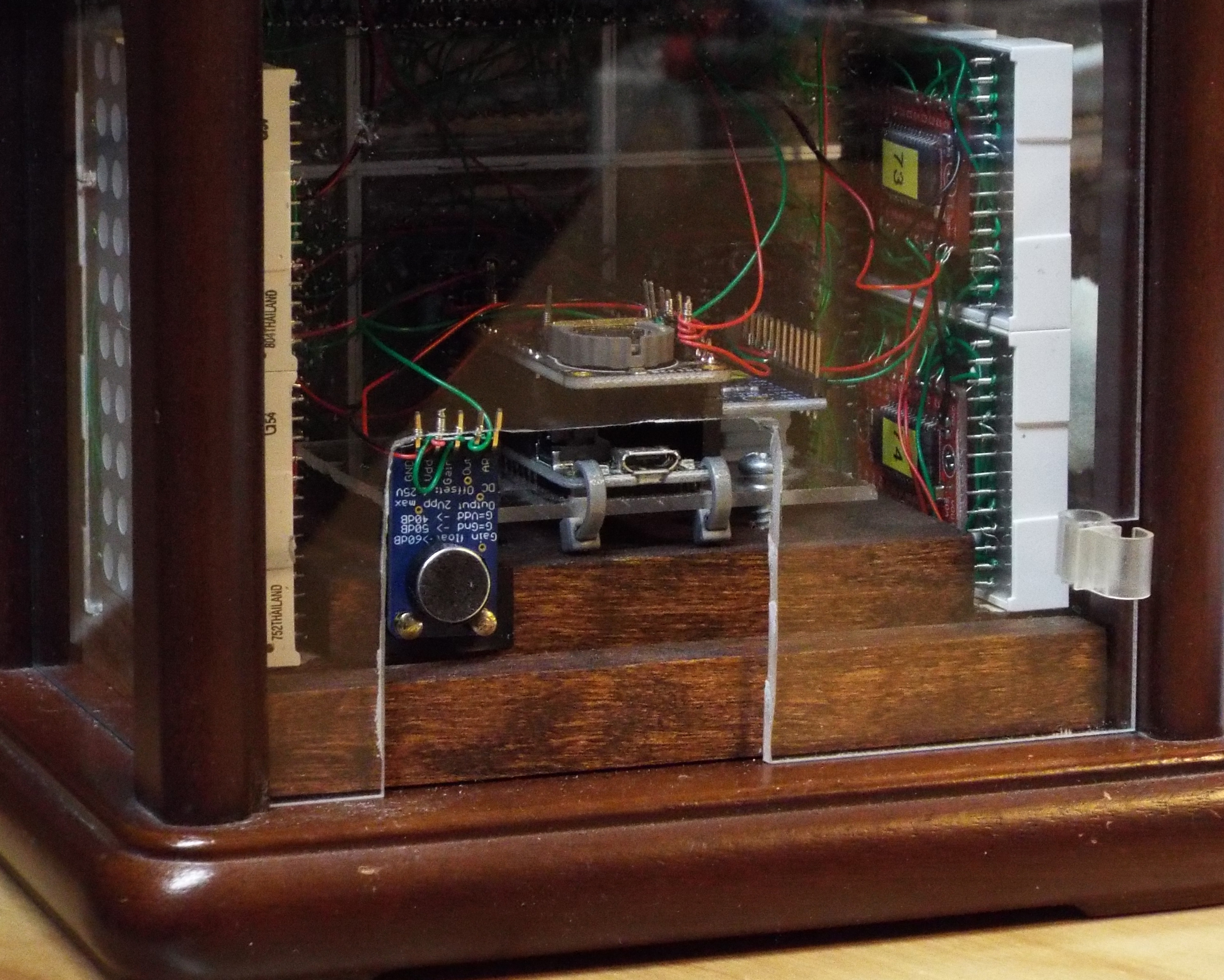
in case of a power failure. The picture below shows the Feather stack with the nRF52832 below and the
DS3231 on top. Also visible is the backup battery. The multiplexer is to the right and
the microphone forward and to the left.
The main controller is an Adafruit nRF52832 Feather (product ID 3406). This has an ARM
Cortex M4F with hardware FPU clocked at 64MHz. It also has a BLE radio. The dot matrix display
is flexible but due to the low pixel density, it's still somewhat limiting. I decided
to use it only to display time and two rows of messages. Adafruit provides a sample
BlueFruit mobile application so I hooked up my software to read commands from the
Bluetooth UART port. Through the mobile app, I can change the color of the time
display (red/green/yellow) as well as the text and color of the two rows of messages.
The text is artificially capped at 60 characters per message. So this is now a clock and
programmable message center.
The side displays have only one third the number of pixels as the front display.
What can I do with them? On a whim, I decided to add a microphone and display the
ambient sound spectrum. This would add some "movement" to the project in the same way that
the original mechanical clock had the turning figurine (as if the scrolling message and
time wasn't movement enough?). An Adafruit MAX9814 microphone
amplifier with electret microphone feeds analog input 2 with ambient room sound.
This is sampled regularly and the spectrum is then displayed on both side displays.
Computing the audio spectum is computationally intensive and even with the hardware FPU,
a 1024 sample FFT still takes a while. I could have opted for a smaller number
of samples to reduce the FFT workload but I wanted frequency details on the low
end of the audio spectrum where all the good stuff is located. The nRF52832 is programmed
using the Arduino IDE but it has some minor differences; one of which is the incredibly
poor resolution of the micro() function at over 970 usec! After some workarounds, I finally
had a loop that acquired 1024 samples at roughly 43,500 Hz in about 23.5 milliseconds.
This creates 512 bins of FFT
data 42.5Hz apart. Since I have 8 columns of LEDs, I opted to display bands corresponding
to 85, 170, 340, 680, 1360, 2720, 5440 and 10880 Hz. Each bar in the graph shows 5 green,
3 yellow and 2 red pixels corresponding to increasing signal strength - each represents
a signal twice as strong as the previous LED from bottom to top. The left and right panels
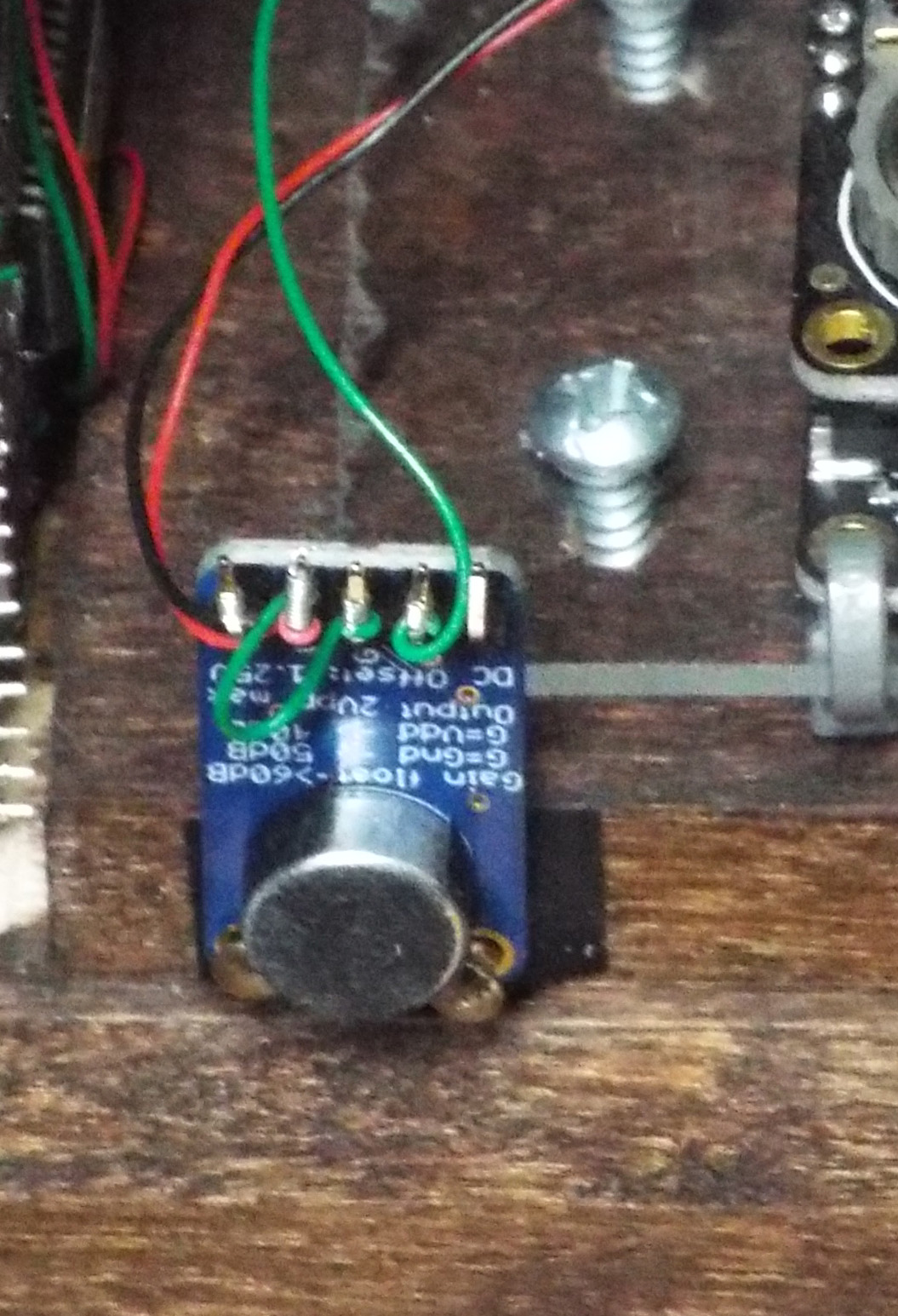
show the same data. The picture below is a closeup of the mic board. It sends an
amplified signal with a 1.25V bias and 2V peak to peak (0.25V to 2.25V). The analog input
is set with a 2.4V reference at 10 bits per sample.
The final adventure for this project is FFT software optimizations.
The first pass of the code using the arduinoFFT library to acquire, compute and display the
data took about 175 ms for 1024 sample. Not exactly earth shattering performance.
I then optimized the code by providing my own version of ComplexToMagnitude() which
only computes the first half of the array (I don't use the other half) and skips the
square root for those 512 bins. The now incorrectly computed magnitude requires a simple
change in the mapping table to the display to make it right again. This shaves off
20 ms to about 155 ms.
A peep at the M4 FPU spec shows that it implements single precision floating point math only.
So I took the arduinoFFT sources and built my own local version using single precision
floating point values instead of doubles. This cut the original time of 175 down to
70 ms. Layering the ComplexToMagnitude() change above only shaves off another
millisecond to 69 ms because the FPU does square roots in hardware in 14 clock ticks.
For further optimizations I have to tackle the remaining part of the FFT that's
expensive - the cosine functions.
I took code from Austin Z. Henley (https://web.eecs.utk.edu/~azh/blog/cosine.html) to
create a local version of the cosine function using lookup tables and linear interpolation.
This was further modified to use single precision floats. I'm now down to about 56 ms.
I might be able to save a few more ticks here and there by localizing and customizing
a few more math functions and writing some custom code to handle the
line rasterizer on the display. But at this point it's not worth it.
To summarize, it takes about 24 ms to get 1024 sample at 43,500Hz (this is fixed time).
I started at 175 - 24 = 151 ms
of FFT processing plus display time; and ended at 56 - 24 = 32ms. The reduction
is 151 - 32 = 119ms or 78% !
That's pretty darn good.
For the actual build, the DS3231 Feather Wing is stacked above the nRF52832 Feather
and fastened to a piece of clear acrylic. This is in turn screwed to a piece of wood,
stained dark brown to match the case. The I2C multiplexer and microphone are mounted
in the adjacent spaces with the mic and micro-USB connection facing backwards. A cutout
in the rear plastic cover lets sound in and USB cable out. Power is supplied
by a off-the-shelf micro-USB wall wart. The LiteOn panels are epoxied together and to the
wood base. The entire assembly is secured to the case by 2 screws from the bottom.
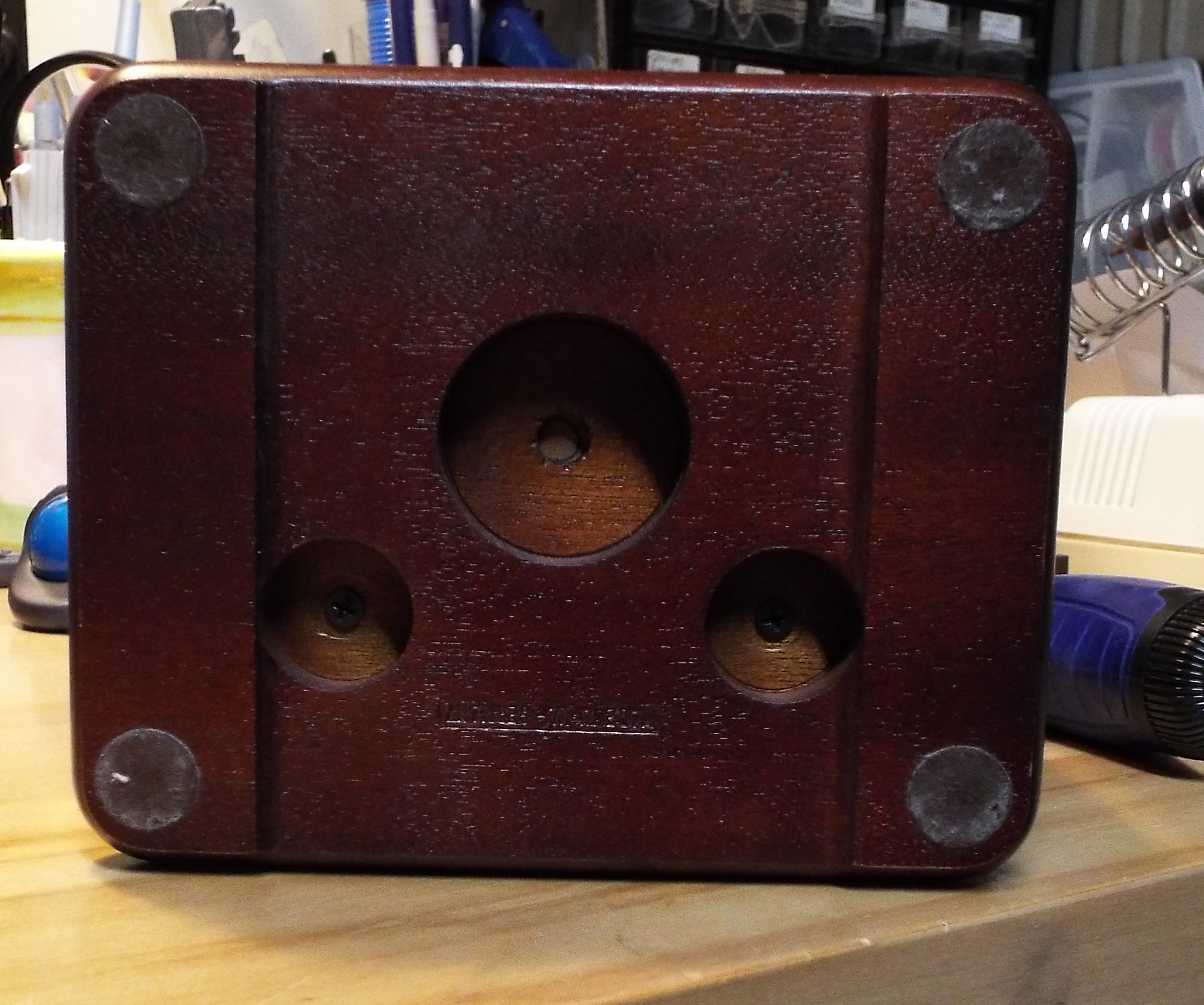
Below are pictures of the wooden sled before and after it's fully populated; and
pictures of the bottom and rear plastic door with cutout.
So that's the story for this clock and message center. And I still have another 24 of those
matrix panel so I gotta think of something to build.
|