|
An Analog Digital Clock
This project began when I saw the web page of
the $1800 McIntosh MCLK12 clock. For those not familiar with McIntosh, it is a high-end audio company
that sells extremely expensive audio gear. Their clock has 2 analog meters made to neatly
match the rest of their product line in both appearance and price. I don't have $1800 to spend on a clock but I do have access to old style analog meters. I finished this in early 2017.
This clock consists of a few simple parts. The
heart of the timekeeping is an Arduino compatible Feather board sold by Adafruit.com. Rather than use
the embedded clock in the Feather, I opted for a high precision RTC Feather Wing. Check with
Adafruit.com to see their latest product offerings. Other electronics components used include (I2C) digital potentiometers, discrete resistors and panel meters.
The meters came on a grey panel and were
purchased at a flea market - $20 for 5 meters or $4 each. Each meter is different - it's made to measure either current or voltage of different ranges and types (AC or DC). I had to gut the internal components inside each meter and create an external
resistor network to allow the digital pots to control each meter accurately. I retained the original
grey panel in the final case. New analog meters can be costly. Aside from the flea market, check out garage sales for unwanted electronics. I've recycled analog meters from cassette tape decks and voltmeters.
I'm not going to provide schematics for
my clock - if you're interested in making something similar, chances are your meters will be
totally different and will require your own custom circuit to interface them to the Feather board.
I'll go over what I did briefly but be aware that a knowledge of electronics is necessary.
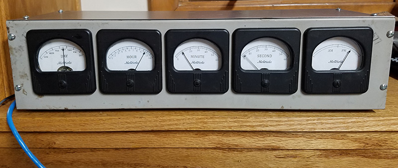
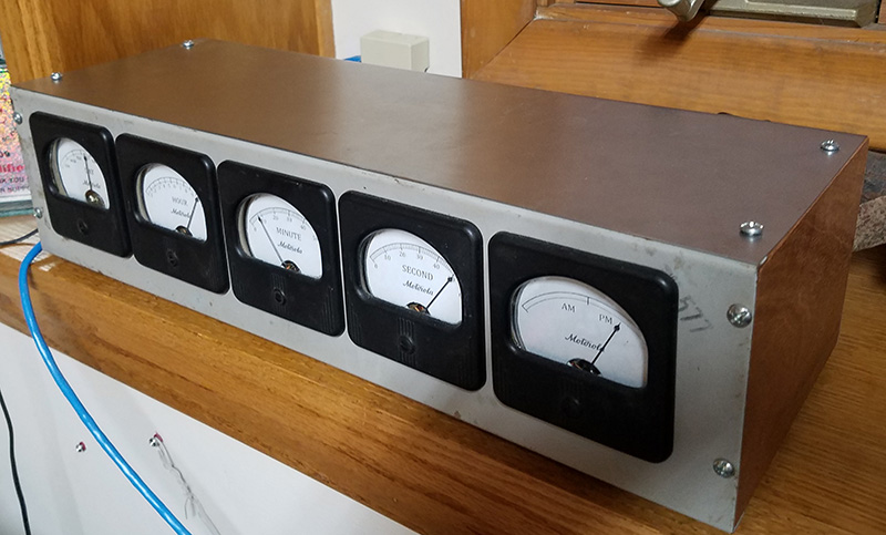
Above is the front view of the completed unit. The
stains on the panel's metal surface are remnants of its past use (wherever that was) so I didn't try
clean it off. From left to right, the 5 meters give the Day (Sunday to Saturday), Hour (1 to 12),
Minute (0 to 59), Second (0 to 59) and AM/PM. Shown is (roughly) Wednesday 10:10:03 PM.
Here's a side view. The unit measures roughly
17-1/2 inches wide, 6 inches deep and 4-1/4 inche tall. The side panels are sold mahogany. The bottom
is 1/4 inch hardboard. The top and back is bent sheetmetal.
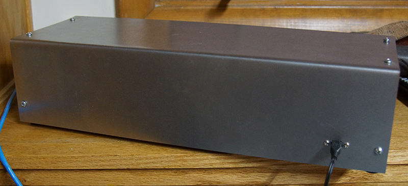
Here's a back view. Four screws on the
top and two on the back hold the sheetmetal to the sides. The only outside connection is a
micro-USB connector. This provides both power (under normal use) and a programming inteface
(for software updates). Power is supplied by a wall-wart USB power supply - the kind used
to charge cell phones.
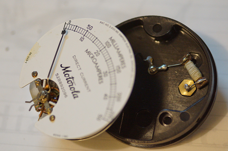
This is a what the insides of a meters looks
like. Naturally, your mileage may vary with yours. This one says "Motorola" but I believe the manufacturer was actually Simpson. The circuitry inside the meter makes the meter measure DC
milliamps up to 250 mA. The existing faceplate are thin metal and held by 2 screws near the bottom.
To change the looks all I had to do was reverse the plate and glue on a new scale printed onto
regular paper. The actual lettering was done with a scanned faceplate and edited in Photoshop.
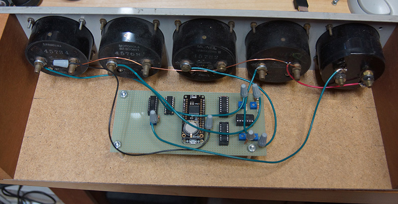
The view inside the box reveals the digital
nature of the clock. The five meters each have 2 bolt connections. All the electronics sit
on a single perforated board. At the center is the Feather Arduino compatible board from
Adafruit and the precision clock Feather Wing above it in a stack. The round backup battery
on the Wing of the clock is visible.
Now comes the fun part. First we'll look at
the right side. The 2 vertically mounted 16 pin
DIP parts are DS1803-010 dual digital potentiometers. These are connected to the Feather via the I2C
bus and provide 256 steps from 0 to 10K ohms. The horizontally mounted 14 pin DIP part is
an LM324 quad op-amp. Together, these three parts allow the control of 4 meters. The fifth meter
is controlled through an additional DS1803-050 (50K digital potentiometer) and
LM324 on the left side. Also visible on the right side are four blue trimmer pots. These, in
conjunction with some hard-to-see resistors, provide the voltages that drive the meters.
A quick theory of operation: the software selects
a digital pot to update by writing a pot value to the correct I2C address of that pot. The
value to be written is driven from a lookup-table that is calibrated for that meter and
its network of resistors. This is time consuming but luckily only has to be done once. For
meters that go from 0 to 59, it means tweaking 60 values. The meters are generally fairly linear
but to get the best results, I found the lookup table to be better than relying on linearity. The
pot sits between 0 and +5V so that's the range of its wiper. This
wiper is used by the op-amp at the (+) input. Each op-amp is
wired as a non-inverting unity-gain buffer to drive the meter (the digital pots can't drive
them directly). The trim pot and other resistors serially connect the output of the op-amp to the (+)
terminal of the meter and reduce the voltage presented to the meter as necessary (this requires
some trial and error when working with unknown parts). The meter's (-) terminal goes to a common ground. Repeat this once for
each meter.
The last piece of the puzzle is the
software. Most of it is pretty straightforward. The only tricky part was writing
the interface to the digital
pots using the existing I2C library. The code loops periodically to update the meter a few times
a second; most of the time it's pausing. At power-up, the code looks for input from the serial
port. If none is found after a timeout period, it reads the contents of the clock chip on the Wing and uses that. If
there is user input, it decodes the string, sets the clock chip and that becomes the new
starting time. Daylight savings time adjustments are pre-programmed into a table for many
years to come - this was easier than calculating the actual days each year.
That's it. This was my first
Arduino (compatible) project and I had a great time building it. It took quite a while
to build mainly because I slowly scavenged meters over many months from different sources until I lucked
out and found those 5 meters in a panel. This also means I have a bunch of odds and ends meters
looking for a project.
So what's next? Since the digital to analog
interface using the digital pots and op-amp can easily be re-used, I have a pair of VU meters
recycled from some old stereo equipment that could make an Analog Digital Weather Station to
display temperature and barometric pressure.
|