|
Trebuchet
|
|
|
Video Clips
|
|
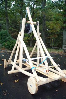
(Completed unit)
|
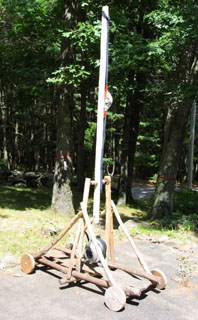
(Rev 2 arm)
|
|
In December
2002, heavy snow tore off a branch from a small maple tree
in our back yard. It was two months before a (relatively)
warm spell allowed us to take a close look at the tree. Unfortunately,
there was a decent amount of damage to the tree so we decided
to cut it down when time allowed.
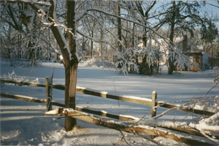
(broken branch in foreground)
We cut the
tree down in February 2003 and it sat in the garage for over
a year while I debated its fate. Nothing worthwhile surfaced
and eventually, I gave the large parts of the tree trunk to
my neighbor to burn in his wood stove. I kept some of the
smaller stock just in case I came up with an interesting project.
Then one
day, for no particular reason, I decided to build a trebuchet.
I begin
each project, big or small, the same way - by defining the
goals. For the trebuchet I wanted:
- something
that would be rustic in appearance
- make
use of the maple sticks
- make
use of any other leftover lumber I already have
- be inexpensive
- work well
While the
actual total construction time was only a few hours, it took
place over the span of many weeks. Small incremental steps
were taken with pauses in-between to consider the next steps.
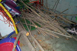
(The original stock of tree branches)

(Stripping and shaving the tree trunk. The smaller branches
made an even bigger mess)
Before
use, the bark from the maple tree was stripped. This actually
took place shortly after the tree was cut down. Suffice it
to say that the process made a mess and since it was winter
at the time, the bark didn't exactly peel off easily.
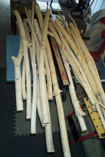
(The pile of sticks to work with)
Taking
into account the available maple stock, I selected pieces
for the major parts of the trebuchet. First was the arm -
it had to be relativelty straight yet be stout enough to support
an axle, weight and rotational forces. The length of the arm
defined the rest of the dimensions.
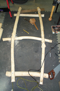
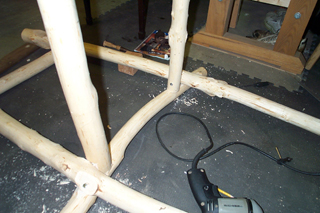
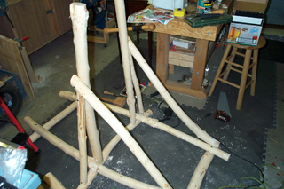
(Top - steps taken starting
with the bottom frame, the side brace, the back brace;
Bottom -
the main verticals, and front brace)
The
basic frame consists of 5 pieces of maple connected with lag
screws. Two vertical posts support the main horizontal axle
for the arm. These posts are braces on three sides to handle
the large stresses of launching a projectile.
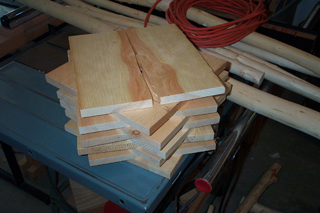
(Stack of broken 12x12 inch pine boards)
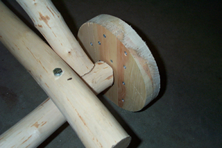
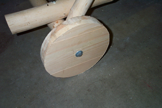
(Inside and outside views of a wheel)
For
this trebuchet, I wanted to use wheels. Not only would wheels
give the unit more throwing distance but it would also make
the unit more mobile. For wood, I decided to make use of 12x12
pine I broke during karate class tests. I sawed the boards
into strips. Each wheel is made of two layers of pine set
perpendicular to each other. A bunch of 1-1/4 inch screws
hold the layers together. A single lag screw holds each wheel
in place.
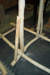
The axle
proved to be quite tricky. My original plan was to power the
trebuchet with about 40 pounds of weight so I needed sturdy
parts everywhere. The main vertical posts were very rigid
and more than capable of holding the weight. What worried
me was the rustic nature of the lumber - there are no straight
line to work with; everything will have to be fitted on the
spot.
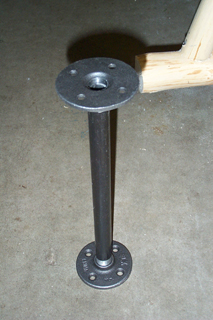
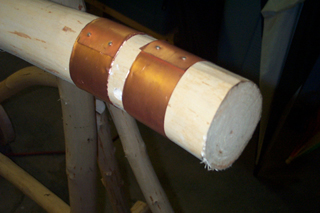
(The bare essentials - the
axle and the arm)
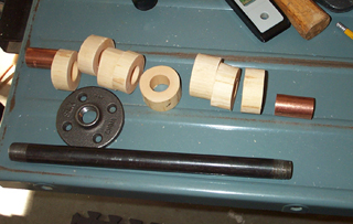
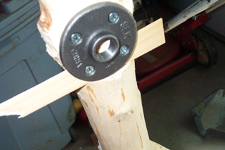
(The parts that make up
the axle; a flange shimmed for alignment)
I
spent quite some time at the local Home Depot, until I found
my axle in the plumbing department. The axle consists of a
metal pipe threaded at both ends, two flanges to hold the
pipe, two short pieces of copper pipe as spacers to give me
clearance to screw in the flanges, and a series of wooden
spacers as additional seperators.
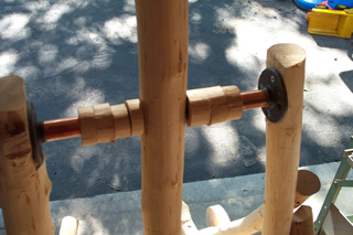
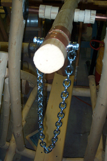
(The assembled axle and arm)
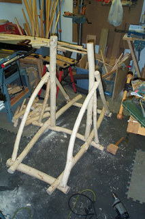
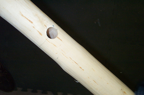
Each
vertical post was hacked to provide a roughly vertical surface
on which to mount the flanges. A single hole was drilled through
the arm to fit the axle. Everything else was threaded onto
the pipe. The wooden disks were waxed to minimize friction.
The final assembly was shimmed on each side and screwed into
place.
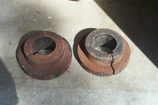
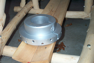
(Weights. What are we ?)
The next big challenger was the weight mount. I considered
a number of inexpensive alternatives - gravel and sand were
the most promising. However each required a strong container;
one strong enough to withstand the dynamic forces that would
be present. What I really wanted to use were metal barbells
weights but that would go against the keep-it-cheap goal.
Then one day, we came across these strange looking metal objects
at the town recycling center. They each weigh 30 pounds and
best of all, the price was right :) A little sandpaper and
spray paint took care of the rust.
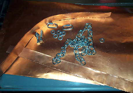
(Left - parts that make up the chain; right - the assembled chain)
The original plan was to thread a single rod through the arm
and attach a chain from both sides. Finding the right parts
with the right dimensions for this turned out to be harder
than I expected so I went to plan B. Two lag screws and some
washers now hold a 36 inch metal chain. The length of the
chain is adjustable via a QuickLink. This method also allows
the weight to be stored seperately and mounted only when needed;
a safer way to move and store the trebuchet.
To protect the arm, copper ferrules were added around each
drilled holes. Truth be told I question how strong my ferrules
are - they're made from copper sheets and might well tear
at the nail that holds them in place. I do like the looks
though :)
Update 19-October-2005
It's
been almost a year since I last touched this thing. Two weeks
ago, we took it outside and launched all sorts of projectiles
- mostly apples, potatoes, tennis balls and a orange. We learned
a few things and brought the contraption back in for its final
touches.
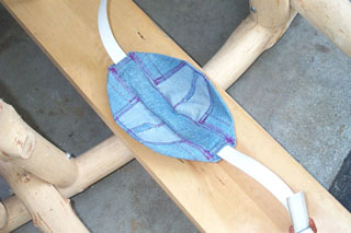
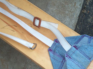
(The projectile basket
and adjustable sling)
I
was going to use an old pair of jeans to make the sling. My
wife handed me a spool of belting - a lining material used
on the inside of belts. She inserted grommets on both ends
and the result is a very strong and flexible sling. The basket
which holds the projectile is from the old jeans. It is sewn
slightly cupped to help hold the projectile. The belting snakes
through a center channel. To allow some level of adjustments,
the belting ends in a metal D-ring and doubles back. As the
sling is lengthened or shortened, the basket is moved along
the belting to the desired location. A single staple locks
it to the belting.
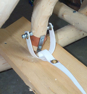
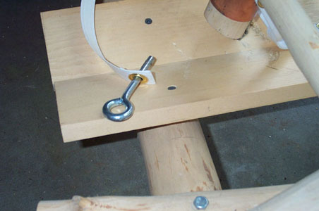
(Connecting and releasing
the sling)
On
the "arm" end, the sling is attached to the arm
on both sides of the arm. This arrangement gives a balanced
force on the sling so it doesn't swing left or right too much.
The D-ring connects to a small metal bar screwed to the end
of the arm. The shape of this metal bar is important - it
determines the release angle of the sling. Release the sling
to early and the projectile may go straight up. Release it
to late and it will drive straight into the ground. The hard
part is getting an angle that can still catch the D-ring yet
release it early enough for a proper projectile flight path.
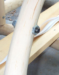
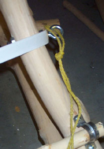
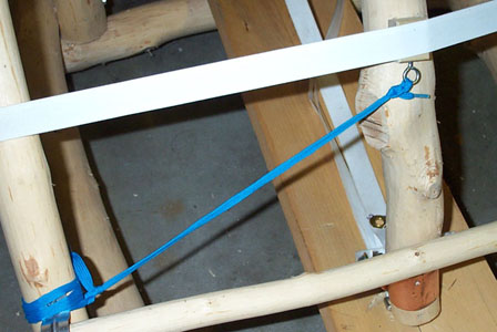
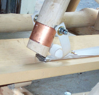
The
trigger mechanism also uses belting material. A piece of belting
with grommets on each end is stretched across the path of
the arm. One side is screwed into the wooden support beam.
The other side is held in place by a cut-off bolt. A short
piece of 1/2 inch plumbing pipe is inserted into the support
beam; screws hold it in place from both sides. The threaded
portion of the bolt has been cut off and the end ground round
(for safety). To arm the device, the bolt (key) is placed
through the grommet and into the plumbing pipe. Pulling the
rope on the key releases the belting and thus the arm. Automotive
grease is used to lubricate the key. To make it easier to
arm, the trigger belting does not have to be extremely taut
when the key is inserted. An additional spacer (a block of
wood) is inserted between the arm and the trigger to force
the arm down to the channel where the D-ring can stay hooked
onto the release bar. A blue shoelace hold this spacer block
to one side of the device so that when it releases, it won't
fly over to the other side of the arm and get tangled up with
the sling's path of motion.

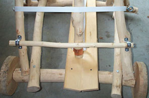
(Two weights and safety bar)
It
became obvious from the trial runs that a single 29+ pound
weight just wasn't enough. So the second weight was sanded
down and painted (black this time; ran out of silver paint!).
One weight is dangerous enough; two is even more so. A safety
bar is installed at the bottom of the arm's path to prevent
accidental firings. Metal 1 inch pipe clamps loosely hold
it in place.
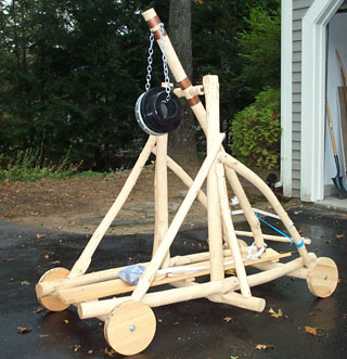
(Completed unit)
That's
it !
Update 10-July-2010
For the past few years, the trebuchet has been stored outdoors under a plastic tarp. Needless to say, this was not the best environment for wood. There were cracks in the timbers and rust was starting to show on some of the metal hardware. It was still in usable shape but I knew it wouldn't last much longer. For the past few years, we've taken the unit to our local school for an annual launch of fruits and vegetables (donated by the local Stop & Shop). The 5th grade kids did a unit on simple machines via catapults and other similar devices. So in June 2010 we took the trebuchet to the Mill Pond school for one last show and tell. See the video at the top of the page.
But before retirement, I made one last change - the Rev 2 arm.
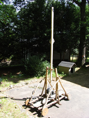
The arm on the trebuchet had always been too short. It's length was originally dictated by the length of the wood I had on-hand when the maple tree blew over. I'd always wondered if the unit would perform better with a longer arm. So with the eminent retirement, I made Rev 2 in about 10 minutes. The old arm was removed and a new 8 ft arm made from a 2x3 was added. I didn't bother to length the sling since that would have required more than the few minutes I wanted to invest.
Subjectively, I think the new arm led to a slightly better release point for the sling for more consistency on throws but the overall throw distance didn't really change that much. I made no changes to the release hook angle; but since the arm is longer, the angle is not as steep and that alone will tend to hold the payload better at launch time.
We unloaded some potatoes and apples with the new arm, shot a video, then disassembled the unit. It was a blast! |