|
 3-Way High Efficiency Speaker
(Lavoce, Dynaudio, Foster 3-way. October-2023)
LCR MTM 3-Channel Speaker
(Three MTM Speakers in One. July-2023)
Mini7bt - A Minimus 7 Portable Bluetooth Speaker
(Minimus 7 and Dayton Audio. Spring-2022)
2-Way Ribbon Tweeter Speakers
(Vifa and Pioneer. May-2020)
Transmission Line Speakers
(Aborted attempt at a TL. September-2012)
Acoustic Research AR-4x Rehab
(Rehab of a garage sale find. January-2016)
Infinity RS-4000 Rehab
(Rehab of a garage sale find. June-2015)
Polaris
(A tall, thin, upwards firing omnidirectional speaker. May-2010)
Shiva_PR15
(A powered subwoofer using a 12" driver and 15" passive radiator. Jan-2010)
Can-Less
(A computer speaker; redux. December-2005)
Can-Can
(A computer speaker in a light canister. Jan-2005)
Sonosub
(10" vented subwoofer in a cardboard tube, powered by a Parapix amp. May-1999)
MTM Center Channel Speaker
(A Madisound design. Nov-1997)
2-way Surround Speakers
(5" woofer and 1" tweeter. July 1997)
3-piece mini system
(6" DVC bass module mated to 4" car speaker. June 1997)
3-way Vented Floorstanding Speaker
(vented 10" woofer, 5" mid and 1" tweeter in a 4
ft tower. Summer 1995)
NHT1259 Subwoofer
(A 12" woofer in a sealed architectural pedestal. Winter 1994-95)
Inexpensive Speaker Stands
(Particle board, sand and spray paint. Fall 1994)
2-way satellite
(6.5" woofer and 1" tweeter. Summer/Fall 1994)
| Audio Electronics Related Projects |
900 MHz Audio Receiver
(Better use for bad headphones. Jan-2008)
Buster - A Simple Guitar Amp
(Perfect for the beginner. Jan-2010)
A PC-based Audio Console
(Use a PC to play tunes. Jan-2010)
LM-12 Amp
(Bridged LM-12 opamps. Aug-2003)
CeeDeePee
(A CD player and FM tuner from spare computer parts. Oct-2002)
Quad 2000 4-Channel Amp
(Premade modules by Marantz. May-1998)
Zen Amp and Bride of Zen Preamp
(by Nelson Pass. Apr-1997)
Using Wood in Speakers FAQ
(Work in progress)
MDF FAQ for speaker builders
Woodworking Tools for the DYIer
(HomeTheaterHiFi.com Oct-1998)
Some Thoughts on Cabinet Finished for DIY Speakers
Large Grills Made Easy
Some Parts Suppliers
(Outdated)
DIY Audio Related URLs
Veneering Primer
(by Keith Lahteine)
How to get a Black Piano Finish
(by DYI Loudspeaker List members)
Sonotube FAQ
(by Gordon McGill)
Excerpts from the Bass List
(Oldies but Goodies)
DIY Loudspeaker List Archives
|
|
LM12-based Amplifier
Some projects
just seem to take longer than others; and by the time they're
done, their reason for existing has long since come and gone.
This is what happened to this amplifier - a project that grew
out of a need for some cheap power which eventually turned
into a project to get rid of unused parts. But I'm getting
a little ahead of myself.
History
Back in
the mid 90's when I first started to assemble my NHT1259-based
subwoofers, I reasoned that if I could build a pair of
cheap but reasonably powerful amplifiers, not only would I
save a $ or two, but I'd also have the satisfaction of building
it. A few other DIYers had successfully built subwoofer amps
using dual LM12 op-amps in a bridged configuration. I obtained
three free samples from National Semiconductor (free is always
good for the DIYer !) and decided to start construction.
Some plans
just don't seem to work out no matter how hard one tries.
In this case, I had trouble getting all the parts I needed,
especially a large enough heatsink and transformer. Oh, did
I say I wanted them cheap ? Ideally, I wanted a transformer
that would deliver about 20 to 22V (40VAC CT) with a decent
amount of current (8A min). This would yield a DC voltage
near the maximum normal operating range of the LM12. A standard
48VAC CT transformer would be to large, and some DIYers had
run into device failures when pushing the standard LM12 (there
are some higher voltage parts available). Getting a transformer
of suitable size is normally not a big deal, but getting it
cheap and not having a timetable for the project meant that
I never found what I wanted. I couldn't find any in the surplus
outlets and I dismissed the thought of unwinding a large transformer.
Over time,
my NHT1259 subwoofers were done and put into service. I no
longer needed this amp and so the plans were shelved. In the
late 90's Adire
Audio released their Shiva subwoofer driver and offered
the DIY Speaker List an introductory special. I decided that
a dedicated subwoofer for a home theater LFE channel would
be something neat to build and so the LM12 amp had a new purpose
in life. As luck would have it, my overall home theater project
never came to be and so I now have both the Shiva and the
LM12 project sitting on ice.
On the parts
front, I stumbled across some large heatsinks with predrilled
TO-3 holes in a surplus outlet in Manchester NH. My project
suddenly was alive... well sort of. The final piece of the
puzzle came from Surplus
Sales of Nebraska. They had a 38VAC CT transformer rated
at 10 A for $35. Now that I had all my parts, I started assembly.
Things immediately ground to a halt when I prototyped a single
op-amp circuit. The gain was set to just 3 and the resulting
noise was pretty bad. Dissapointed, I put off the project
rather than taking the time to debug it; what's the rush since
it's been so long already ? I picked up the project and this
time set the gain to 20 (a more reasonable value for an amp).
I cleanup the connections and things sounded pretty good.
Before continuing, I decided to envision the entire thing
- what would the completed amp look like ? Can I use it as
a unit mounted into the rear of a subwoofer (like a "plate"
amplifier) ? What about a preamp circuit for level matching
? What about EQ for the sub ? All these design questions once
again stalled the project.
Meanwhile,
the Shiva project lumbered
along at a turtle's pace. It too lacked direction and spent
most of its time either collecting dust or sitting in a test
box that in turn collected dust. Without my desired home theater
setup visible in the near future, there was no incentive to
work on the subwoofer. The further complicate matters, the
original plan of building a passive radiator subwoofer in
a small box now seemed less than ideal. The simulation response
curves weren't all that I wanted for the box size I had hoped
for... it was all going nowhere.
Reality
finally set in. I had to put these projects aside to make
room for other projects; and the best way to do that was to
finish them. With some unresolved questions still lurking
in the background, the smart thing to do seemed to be to package
up both the LM12 and the Shiva project into a semi-finished
state in the quickest, most cost effective manner. For the
LM12, this meant housing it so that it could be used if necessary
but not in anything fancy in case I ever decide to re-house
it some day. So here it is, two large heatsinks bolted together,
then screwed to a piece of plywood. The enclosure has 4 sides.
It is missing a top and most of the back. It is fully wired
but has not preamp, crossover or EQ functionality. All that
is for the future, whever that is !
Construction Details
The details
here are a little sparse because, frankly, there's not much
to say !
The design
is the basic LM-12 amplifier circuit as published in the LM-12
specifications from National
Semiconductor. I used the bridged design, using two LM12s
for a single channel (one inverted, one non-inverted). The
voltage gain is set to 20.
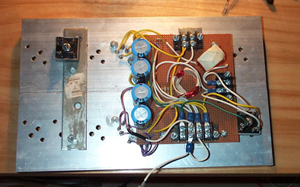 This is the heatsink assembly.
The circuit board doesn't hold much - just a few passive parts
and electrical connectors. I could have easily bolted a few
terminal strips to the back of the heatsinks and performed
the same point-to-point wiring but this looks a little cleaner.
The are three sets of screw terminals. Towards the bottom
is a set of four for the power supply. The (+, -, and two
for ground). The two screws near the top is the input signal.
Finally, the two near the right edge is the output to the
speaker. The bridge rectifier on the right is on the output
to the speakers. The unconnected bridge rectifier on the left
is for the main power supply. The heatsink is electrically
isolated from all components (bridges and LM12).
This is the heatsink assembly.
The circuit board doesn't hold much - just a few passive parts
and electrical connectors. I could have easily bolted a few
terminal strips to the back of the heatsinks and performed
the same point-to-point wiring but this looks a little cleaner.
The are three sets of screw terminals. Towards the bottom
is a set of four for the power supply. The (+, -, and two
for ground). The two screws near the top is the input signal.
Finally, the two near the right edge is the output to the
speaker. The bridge rectifier on the right is on the output
to the speakers. The unconnected bridge rectifier on the left
is for the main power supply. The heatsink is electrically
isolated from all components (bridges and LM12).
|
|
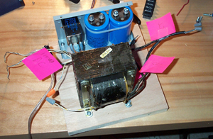 This is the power
supply assembly. The pink PostIt notes identify the transformer's
secondary to be used by the LM12s. There is also another unused
secondary winding (orange and grey wire nuts on the left side).
The metal plate near the top is part of an old ATX computer
power supply. I originally intended to mount various components
in the ATX chassis but decided at the last minute to scrap
the idea. I ended up using part of it so that I could easily
mount an EIC receptable, an accompanying line filter and the
main power supply caps. Since this whole box is temporary,
it's no big deal.
This is the power
supply assembly. The pink PostIt notes identify the transformer's
secondary to be used by the LM12s. There is also another unused
secondary winding (orange and grey wire nuts on the left side).
The metal plate near the top is part of an old ATX computer
power supply. I originally intended to mount various components
in the ATX chassis but decided at the last minute to scrap
the idea. I ended up using part of it so that I could easily
mount an EIC receptable, an accompanying line filter and the
main power supply caps. Since this whole box is temporary,
it's no big deal.
|
|
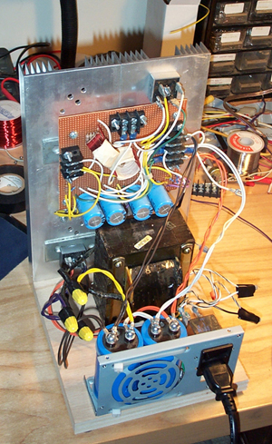 The heatsink assembly
is screwed to the plywood base of the power supply assembly.
Two screws is all it takes. All wiring is removable.
The heatsink assembly
is screwed to the plywood base of the power supply assembly.
Two screws is all it takes. All wiring is removable.
|
|
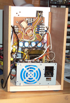 The side panels are
just pieces of plywood. Four rubber feet at added to raise
the unit. The black cable on the left side is connected to
the input screw terminals; the other end has a female RCA
connector.
The side panels are
just pieces of plywood. Four rubber feet at added to raise
the unit. The black cable on the left side is connected to
the input screw terminals; the other end has a female RCA
connector.
|
|
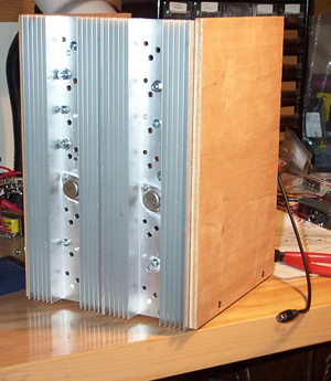 The front view.
|
|
03-August-2003
Note: The
contents in these pages are provided without any guarantee,
written or implied. Readers are free to use them at their
own risk, for personal use only. No commercial use is allowed
without prior written consent from the author.
|
|
 |