|
 3-Way High Efficiency Speaker
(Lavoce, Dynaudio, Foster 3-way. October-2023)
LCR MTM 3-Channel Speaker
(Three MTM Speakers in One. July-2023)
Mini7bt - A Minimus 7 Portable Bluetooth Speaker
(Minimus 7 and Dayton Audio. Spring-2022)
2-Way Ribbon Tweeter Speakers
(Vifa and Pioneer. May-2020)
Transmission Line Speakers
(Aborted attempt at a TL. September-2012)
Acoustic Research AR-4x Rehab
(Rehab of a garage sale find. January-2016)
Infinity RS-4000 Rehab
(Rehab of a garage sale find. June-2015)
Polaris
(A tall, thin, upwards firing omnidirectional speaker. May-2010)
Shiva_PR15
(A powered subwoofer using a 12" driver and 15" passive radiator. Jan-2010)
Can-Less
(A computer speaker; redux. December-2005)
Can-Can
(A computer speaker in a light canister. Jan-2005)
Sonosub
(10" vented subwoofer in a cardboard tube, powered by a Parapix amp. May-1999)
MTM Center Channel Speaker
(A Madisound design. Nov-1997)
2-way Surround Speakers
(5" woofer and 1" tweeter. July 1997)
3-piece mini system
(6" DVC bass module mated to 4" car speaker. June 1997)
3-way Vented Floorstanding Speaker
(vented 10" woofer, 5" mid and 1" tweeter in a 4
ft tower. Summer 1995)
NHT1259 Subwoofer
(A 12" woofer in a sealed architectural pedestal. Winter 1994-95)
Inexpensive Speaker Stands
(Particle board, sand and spray paint. Fall 1994)
2-way satellite
(6.5" woofer and 1" tweeter. Summer/Fall 1994)
| Audio Electronics Related Projects |
900 MHz Audio Receiver
(Better use for bad headphones. Jan-2008)
Buster - A Simple Guitar Amp
(Perfect for the beginner. Jan-2010)
A PC-based Audio Console
(Use a PC to play tunes. Jan-2010)
LM-12 Amp
(Bridged LM-12 opamps. Aug-2003)
CeeDeePee
(A CD player and FM tuner from spare computer parts. Oct-2002)
Quad 2000 4-Channel Amp
(Premade modules by Marantz. May-1998)
Zen Amp and Bride of Zen Preamp
(by Nelson Pass. Apr-1997)
Using Wood in Speakers FAQ
(Work in progress)
MDF FAQ for speaker builders
Woodworking Tools for the DYIer
(HomeTheaterHiFi.com Oct-1998)
Some Thoughts on Cabinet Finished for DIY Speakers
Large Grills Made Easy
Some Parts Suppliers
(Outdated)
DIY Audio Related URLs
Veneering Primer
(by Keith Lahteine)
How to get a Black Piano Finish
(by DYI Loudspeaker List members)
Sonotube FAQ
(by Gordon McGill)
Excerpts from the Bass List
(Oldies but Goodies)
DIY Loudspeaker List Archives
|
|
Zen
Amp and Bride of Zen Preamp
The Zen
amp and preamp I've built are the creation of Nelson Pass.
Reprints of the original published article can be found on
the Pass
Laboratories DIY web site. Refer to those articles for
the theory of operation, electrical details and construction
hints. On this page, I am only going to provide some thoughts
and observations from my experience in building these wonderful
projects.
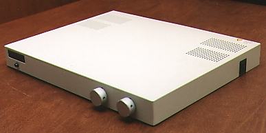 This is my Zen preamp. It is packaged in
an old X-terminal chassis. The two rotary knobs on the front
panel are the volume control and a three input selector switch.
The knobs are brushed aluminum. On the far left of the front
panel is a green neon power lamp. The power switch is on the
right side, towards the rear of the unit. A standard IEC power
connection is used. Not shown is the rear of the chassis which
contains RCA jacks for three pairs of inputs and one pair
of outputs. My only alteration to the original design is the
addition of the input selector switch. As for the actual construction,
my only advice is to splurge on the volume control potentiometer.
My original pot was a cheap one and I got what I paid for.
I ended up with a quality unit from The Parts Connection /
Sonic Frontiers (they no longer carry DIY parts).
This is my Zen preamp. It is packaged in
an old X-terminal chassis. The two rotary knobs on the front
panel are the volume control and a three input selector switch.
The knobs are brushed aluminum. On the far left of the front
panel is a green neon power lamp. The power switch is on the
right side, towards the rear of the unit. A standard IEC power
connection is used. Not shown is the rear of the chassis which
contains RCA jacks for three pairs of inputs and one pair
of outputs. My only alteration to the original design is the
addition of the input selector switch. As for the actual construction,
my only advice is to splurge on the volume control potentiometer.
My original pot was a cheap one and I got what I paid for.
I ended up with a quality unit from The Parts Connection /
Sonic Frontiers (they no longer carry DIY parts).
|
|
I had hoped
to package the Zen amplifier in a similar chassis, but that
proved impossible for several reasons - such as the size of
the transformer, capacitors and heat sink. My final chassis
consists of an old Cabletron network box of some sort, with
a massive heat sink mounted above the cover seperated by four
3/4 inch spacers. The output devices (MOSFETs) are mounted
on the underside of the heatsink.
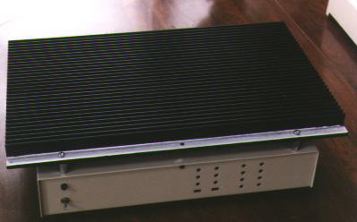 This is the Zen amp viewed from the front.
On the left is a toggle power switch above a green neon power
lamp. The four vertical rows of LEDs just right of center
are currently unused (could turn it into some sort of level
meter).
This is the Zen amp viewed from the front.
On the left is a toggle power switch above a green neon power
lamp. The four vertical rows of LEDs just right of center
are currently unused (could turn it into some sort of level
meter).
|
|
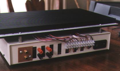 The view from the back shows the RCA input
jacks on the left, followed by the output speaker binding
posts. An IEC power connector is on the far right. The row
of white connectors - 12 pairs in all - connects leads from
the MOSFETs underneath the heatsink to the PCB inside the
box. While not ideal, this setup allowed me to assemble the
pieces seperately and finally connect them electrically.
The view from the back shows the RCA input
jacks on the left, followed by the output speaker binding
posts. An IEC power connector is on the far right. The row
of white connectors - 12 pairs in all - connects leads from
the MOSFETs underneath the heatsink to the PCB inside the
box. While not ideal, this setup allowed me to assemble the
pieces seperately and finally connect them electrically.
|
|
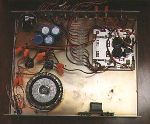 The inside of the chassis shows the toroidal
transformer, power supply capacitors towards the upper left
and PCB on the upper right. The empty space on the lower right
is reserved for whatever will eventually drive the front panel
LEDs.
The inside of the chassis shows the toroidal
transformer, power supply capacitors towards the upper left
and PCB on the upper right. The empty space on the lower right
is reserved for whatever will eventually drive the front panel
LEDs.
The transformer
used is a surplus unit from MECI.
It is rated at 2 X 24 VAC at 4 amps each. The circuit built
uses the PCB from Old
Colony Sound Labs which is the original Zen design without
modifications presented in The Return of Zen. The most
troublesome part of this project was finding an adequate heatsink.
The two MOSFETS in each channel dissipate about 70 watts of
heat. Since I did not want to deal with fan noise, I needed
sufficient heat sinking for 140 watts. The heat sink I used
is from a surplus store and weighs a LOT ! At idle, the center
of the heatsink reached 127.2 degrees Farenheit in a room
with an ambient temperature of 65 F. It took just under 45
minutes to reach equilibrium. Note that the heatsink is not
mounted optimally - convection is much better if its lengthwise
fins were mounted vertically. My arrangement is a compromise
of available chassis and heatsink.
The sound
of the Zen amp and preamp are superb. In the spirit of the
Zen designs, the less said the better.
Update
5-February-2002
A funny
thing happened recently. I had the Zen preamp hooked up to
my computer and noticed that some of my waveforms were clipped
on the negative half of the waveform. This didn't happen all
the time, only in some obscure cases. After some analysis,
I determined that at higher input voltages, both channels
would clip as I had seen.
The fix
was pretty simple. With a 1.4 V RMS input (2 V Peak to Peak,
the most I plan to deliver to this preamp) I adjusted trimmers
P102/P202 until the output no longer clipped. This turned
out to be a little more then 7 V at the gate of Q101/Q201.
I eventually set the trimmers to deliver 6.92 V. This value
used to be 8 V in the original design. The output will now
swing unclipped at just under +/-10V with the full 1.4 V RMS
input. I suspect this will increase distortion but I haven't
done any distortion measurements yet.
|
|
02-February-2002
Note: The
contents in these pages are provided without any guarantee,
written or implied. Readers are free to use them at their
own risk, for personal use only. No commercial use is allowed
without prior written consent from the author.
|
|
 |